Control device

a control device and lighting technology, applied in the field of functional and decorative lighting, can solve the problems of not being easily expandable, and forming a quite ugly piece such as, e.g., a huge television s

Active Publication Date: 2013-11-07
KONINKLIJKE PHILIPS ELECTRONICS NV
View PDF3 Cites 3 Cited by
  • Summary
  • Abstract
  • Description
  • Claims
  • Application Information

AI Technical Summary

Benefits of technology

[0005]It is an object of the present invention to overcome this problem, and to provide lighting that is decorative. It is a secondary object to provide lighting that is functional.
[0007]The control device is connectable to any one of the plurality of lighting elements, which is advantageous in that very flexible lighting is achieved, since it is easily extendible and scalable. Furthermore, no central control is necessary. Instead, the position of the control depends on the position of the control device.
[0010]The control device may be arranged to activate said at least one lighting effect upon receiving an indication from a detector, wherein said detector is at least one of the group of: a light sensor, a vision-based sensor, a weather sensor, a color sensor, a fragrance sensor, a humidity sensor, a temperature sensor, a movement detector, a heat detector, a microphone coupled to means for speech recognition, and a camera. In this way, energy can be saved in that the lights are not lit when there is nobody in the vicinity of the control device and the lighting elements. As an alternative, magnificent lighting applications can be created including, e.g., that lighting elements light up only when a person goes past them.
[0011]The control device may be arranged to activate said at least one lighting effect when the control device is connected to said lighting element. This is advantageous in that the lighting effect may start automatically upon connecting the control device to the lighting element.
[0012]The control device may comprise at least one input means for operating the at least one lighting effect of at least one lighting element of the plurality of interconnected lighting elements. This is advantageous in that it is easy to operate the at least one lighting effect of at least one lighting element of the plurality of interconnected lighting elements.
[0016]The control device may incorporate at least one of the group of: a radio receiver, a television receiver, and a connection to the Internet. This is advantageous in that the control device can be remote-controlled.

Problems solved by technology

Once installed, it is not easily expandable, and when not in use, it may constitute a quite ugly piece such as, e.g., a huge television set.

Method used


Image

  • Control device
  • Control device
  • Control device

Examples


Embodiment Construction

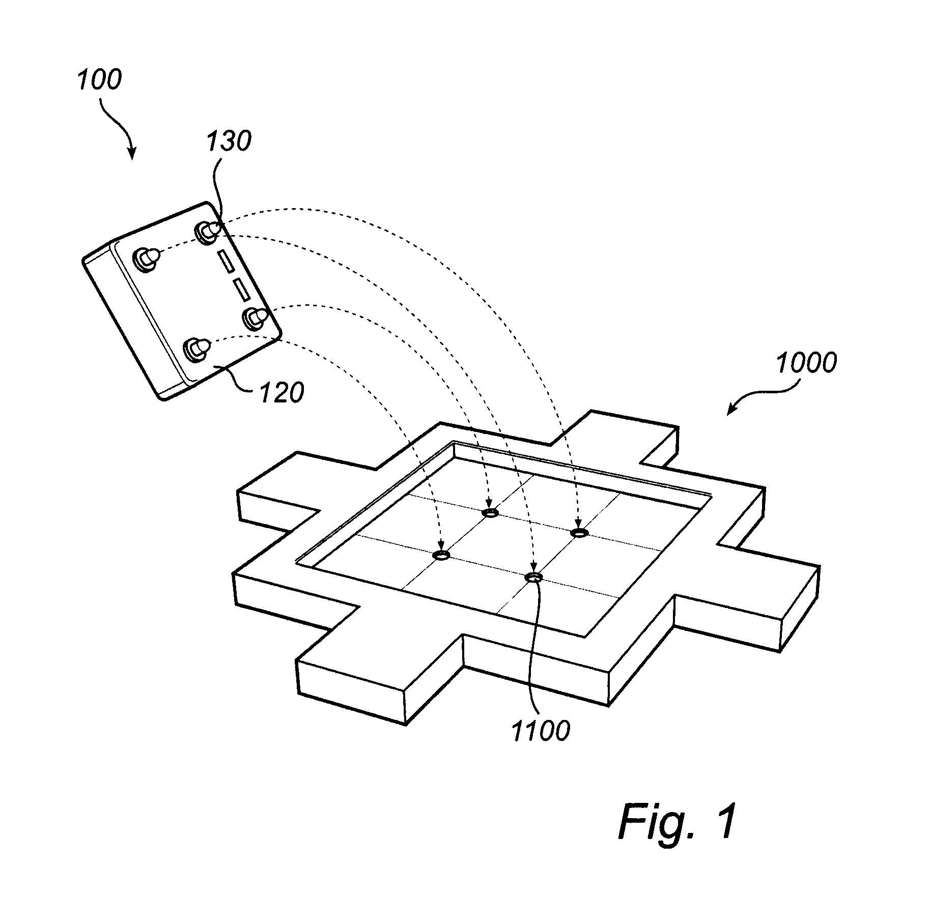
[0031]FIG. 1 illustrates a rear side 120 of an embodiment of a control device 100. FIG. 1 further discloses a lighting element 1000. The control device 100 is arranged to be connected to the lighting element 1000 by means of at least one attachment part 130. In this specific embodiment, the control device 100 comprises four attachment parts 130. The at least one attachment part 130 is arranged to be connected to at least one receiving part 1100 in the lighting element 1000. In this specific embodiment, the lighting element 1000 comprises four receiving parts 1100. The at least one attachment part 130 may be clicked or snapped into the at least one receiving part 1100. The at least one attachment part 130 may be a magnet and may be magnetically connected to the at least one receiving part 1100, which in such a case is made of a ferromagnetic material. Alternatively, the at least one attachment part 130 and the at least one receiving part 1100 may be made of hook and loop fasteners, s...


PUM


Abstract

The disclosed embodiments relate to functional and decorative lighting. At least one control device (200a, 200b) is connected to a plurality of lighting elements (2000). The control devices (200a, 200b) are arranged to control lighting effects of the plurality of lighting elements (2000).

Description

FIELD OF THE INVENTION[0001]The present invention relates to functional and decorative lighting.BACKGROUND OF THE INVENTION[0002]There are several means for displaying and supplying information, such as, e.g., signs, posters, television, interactive screens, etc. It is generally desired that the information is displayed both clearly and decoratively.[0003]Usually, the means used for displaying information is quite static. Once installed, it is not easily expandable, and when not in use, it may constitute a quite ugly piece such as, e.g., a huge television set.[0004]There is thus a need to improve the means used for displaying information in terms of flexibility, etc.SUMMARY OF THE INVENTION[0005]It is an object of the present invention to overcome this problem, and to provide lighting that is decorative. It is a secondary object to provide lighting that is functional.[0006]According to a first aspect of the invention, this and other objects are achieved by a control device for contr...

Claims


Application Information

Patent Timeline
Patent Type & Authority Applications(United States)
IPC IPC(8): H05B37/02
CPCH05B37/02H05B45/20H05B47/10H05B47/105H05B47/115H05B47/155H05B47/175
Inventor VAN DE SLUIS, BARTEL MARINUSKNAAPEN, BRAMBERGMAN, ANTHONIE HENDRIK
Owner KONINKLIJKE PHILIPS ELECTRONICS NV
Why Eureka
Try Eureka