Radar receiver, and radar device equipped with same

a radar device and receiver technology, applied in the direction of measuring devices, using reradiation, instruments, etc., can solve the problems of short distance to the other vessel, jamming other radar devices installed on the host vessel or other vessels as interference images, and low noise amplifier

Active Publication Date: 2014-01-02
FURUNO ELECTRIC CO LTD
View PDF20 Cites 6 Cited by
  • Summary
  • Abstract
  • Description
  • Claims
  • Application Information

AI Technical Summary

Benefits of technology

[0019]Since there is the risk that the low noise amplifier will become unstable due to temperature changes, the power is left on even in the standby mode. This prevent

Problems solved by technology

However, because the magnetron 19 or the local oscillator 5 may become unstable due to temperature changes, they have to be preheated by turning on the power ahead of time, before the transmission and reception of signals.
If the local oscillation signal LO is thus emitted from the antenna 2, there is the risk that it will jam other radar devices installed on the host vessel or other vessels as an interference image.
However, since no transmission or reception of pulse signals is performed when the radar device 1 is in the standby mode, any local oscillation signal LO tha

Method used


Image

  • Radar receiver, and radar device equipped with same
  • Radar receiver, and radar device equipped with same
  • Radar receiver, and radar device equipped with same

Examples


Embodiment Construction

[0029]Selected embodiments will now be explained with reference to the drawings. It will be apparent to those skilled in the art from this disclosure that the following descriptions of the embodiments are provided for illustration only and not for the purpose of limiting the invention as defined by the appended claims and their equivalents.

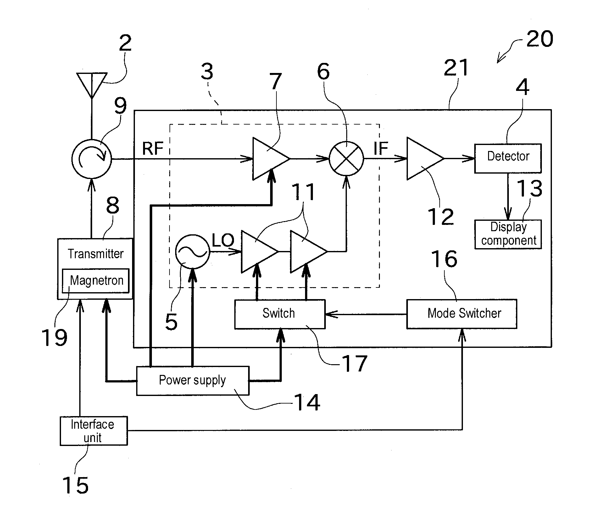
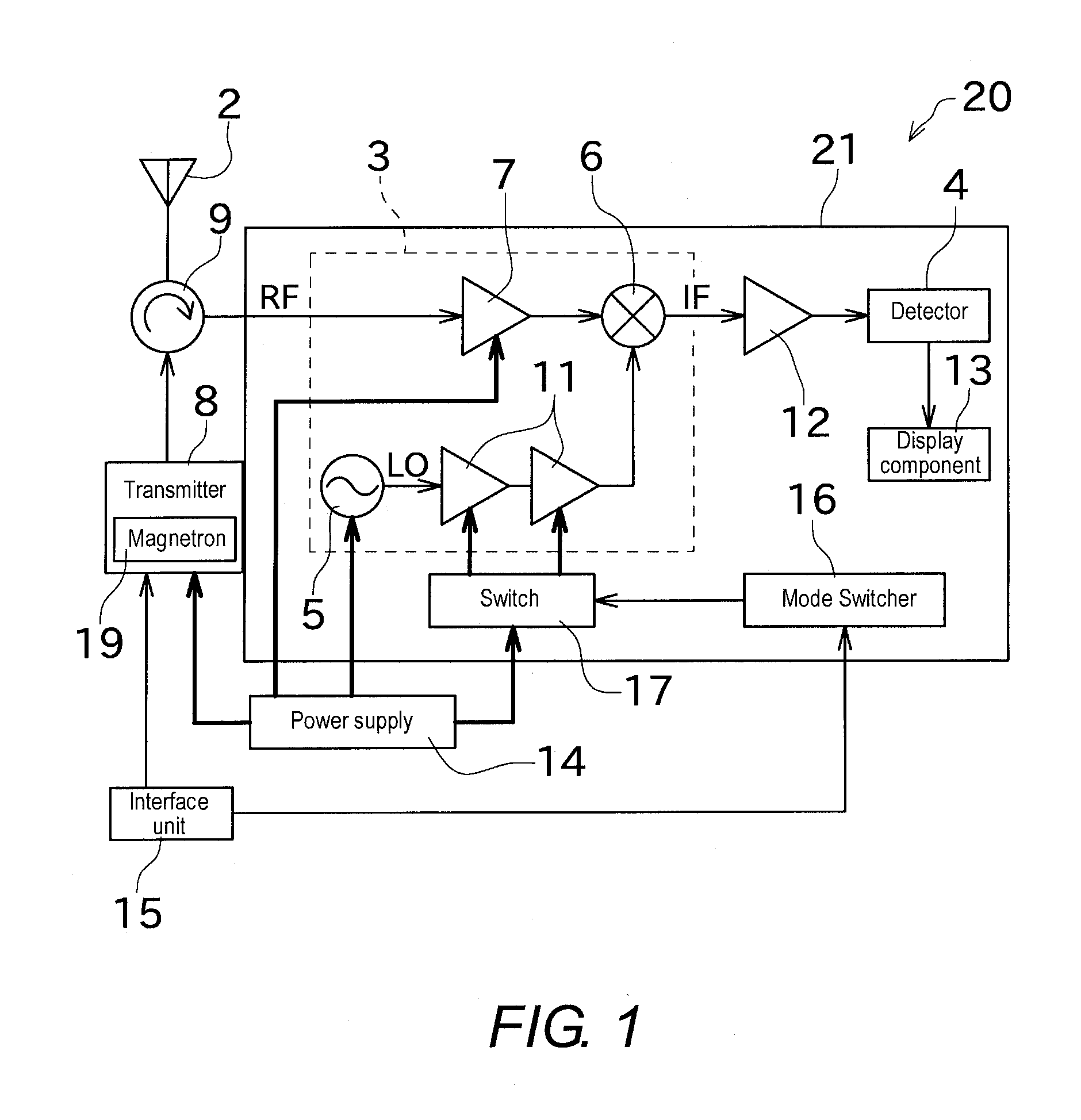
[0030]An embodiment of the present invention will now be described through reference to the drawings. A radar device 20 in this embodiment (shown in FIG. 1) is a marine-use pulse radar device, and includes a radar antenna 2, a transmitter (radar transmitter) 8, a circulator 9, a receiver (radar receiver) 21, an interface unit 15, and a power supply 14.

[0031]The transmitter 8 includes an oscillator formed by a magnetron 19, which produces a high-frequency pulse signal (transmission signal) at a specific period, and applies this signal to the radar antenna 2. Consequently, the pulse signal is emitted from the radar antenna 2. The radar antenna 2 has...


PUM


Abstract

There is provided a radar receiver that effectively prevents local oscillator signals from leaking out from an antenna. A receiver 21 includes a local oscillator 5, a mixer 6, a buffer amplifier 11, and a mode switcher 16. The local oscillator 5 outputs a local oscillation signal LO. The mixer 6 mixes a high-frequency signal RF received by a radar antenna 2 with the local oscillation signal LO. The buffer amplifier 11 is disposed between the local oscillator 5 and the mixer 6. The mode switcher 16 switches at least between a standby mode in which power is supplied to the local oscillator 5 and no power is supplied to the buffer amplifier 11 and a reception mode in which power is supplied to both the local oscillator 5 and the buffer amplifier 11.

Description

CROSS-REFERENCE TO RELATED APPLICATIONS[0001]This application claims priority to Japanese Patent Application No. 2012-147297 filed on Jun. 29, 2012. The entire disclosure of Japanese Patent Application No. 2012-147297 is hereby incorporated herein by reference.BACKGROUND[0002]1. Field of the Invention[0003]The present invention relates to a configuration for preventing signals of a local oscillator provided to the receiver of a radar device from leaking out from an antenna.[0004]2. Background Information[0005]A pulse radar device finds a target in the surrounding area by sending high-frequency pulse signals produced by a magnetron or other such oscillator out from an antenna, and using the antenna to receive and detect echoes (reflected waves) that come back from the target. The configuration of a conventional radar device is shown in FIG. 3.[0006]As shown in FIG. 3, the receiver 10 of a conventional radar device 1 generally has a configuration in which a front end 3 is provided ahe...

Claims


Application Information

Patent Timeline
IPC IPC(8): G01S7/03
CPCG01S7/03G01S7/285G01S7/038
Inventor FUNAE, AKIO
Owner FURUNO ELECTRIC CO LTD
Why Eureka
Try Eureka