Magnetic lock

a magnetic key and lock technology, applied in the field of magnetic key locks, can solve the problems of magnetic key not being able to rotate in order to unlock the lock tube with the sleeve, magnetic elements will be forced to damage, and the lock tube is normally locked within the sleeve, so as to prevent any damage to the magnetic key lock, minimize manufacturing costs, and economic and efficient

Inactive Publication Date: 2014-09-11
TSAI LINCLON +3
View PDF20 Cites 11 Cited by
  • Summary
  • Abstract
  • Description
  • Claims
  • Application Information

AI Technical Summary

Benefits of technology

[0009]Another advantage of the invention is to provide a magnetic lock, wherein the lock body can be freely rotated at 360° within the lock cavity of the lock sleeve, such that when an uncorrected key or other elongated object is inserted into the keyway, the lock body will only be free-rotated to prevent any damage of the magnetic key lock by the excessive rotational force of the uncorrected key.
[0010]Another advantage of the invention is to provide a magnetic lock, wherein the latch actuator is actuated not only to rotate corresponding to the rotation of the actuation key but also to move longitudinally along the axis of the actuation key in order to actuate the latch assembly.
[0011]Another advantage of the invention is to provide a magnetic lock, which can incorporate with different types of latch assemblies, such as a fuel tank cap lock or a door latch assembly.
[0012]Another advantage of the invention is to provide a magnetic lock, which does not require to alter the original structural design of the latch assembly, so as to minimize the manufacturing cost of the latch assembly incorporating with the magnetic lock of the present invention.
[0013]Another advantage of the invention is to provide a magnetic key lock, wherein no expensive or complicated structure is required to employ in the present invention in order to achieve the above mentioned objects. Therefore, the present invention successfully provides an economic and efficient solution for providing a safe configuration for the latch assembly.

Problems solved by technology

One disadvantage of the conventional magnetic key lock is that the lock tube is normally locked up within the sleeve.
Therefore, when an object, such as an uncorrected magnetic key, is inserted into the lock tube, such magnetic key cannot be rotated in order to unlock the lock tube with the sleeve.
However, when an excessive rotational force is applied to the object, the magnetic elements will be forced to damage so as to unlock the lock tube with the sleeve.
Otherwise, the object may be deformed or broken by the excessive rotational force.
Once the broken part of the object is left within the lock tube, the entire of the magnetic key lock cannot be actuated anymore.
Another disadvantage of the conventional magnetic key lock is that when a key with a relatively strong magnetic field, such as a universal magnetic key, is inserted into the lock tube, the strong magnetic field of such key will interfere with the magnetic elements.
Another disadvantage of the conventional magnetic key lock is that after the magnetic arrangement is actuated by the actuation key, the actuation key is rotate to actuate the latch assembly.
In addition, the conventional magnetic key lock can only transmit the rotational force from the actuation key to the latch assembly through the sleeve and the lock tube, such that the latch assembly will be actuated by the rotational force only.
In other words, the conventional magnetic key lock will limit the structural configuration of the latch assembly so as to limit the practical use of the latch assembly.

Method used


Image

  • Magnetic lock
  • Magnetic lock
  • Magnetic lock

Examples


Embodiment Construction

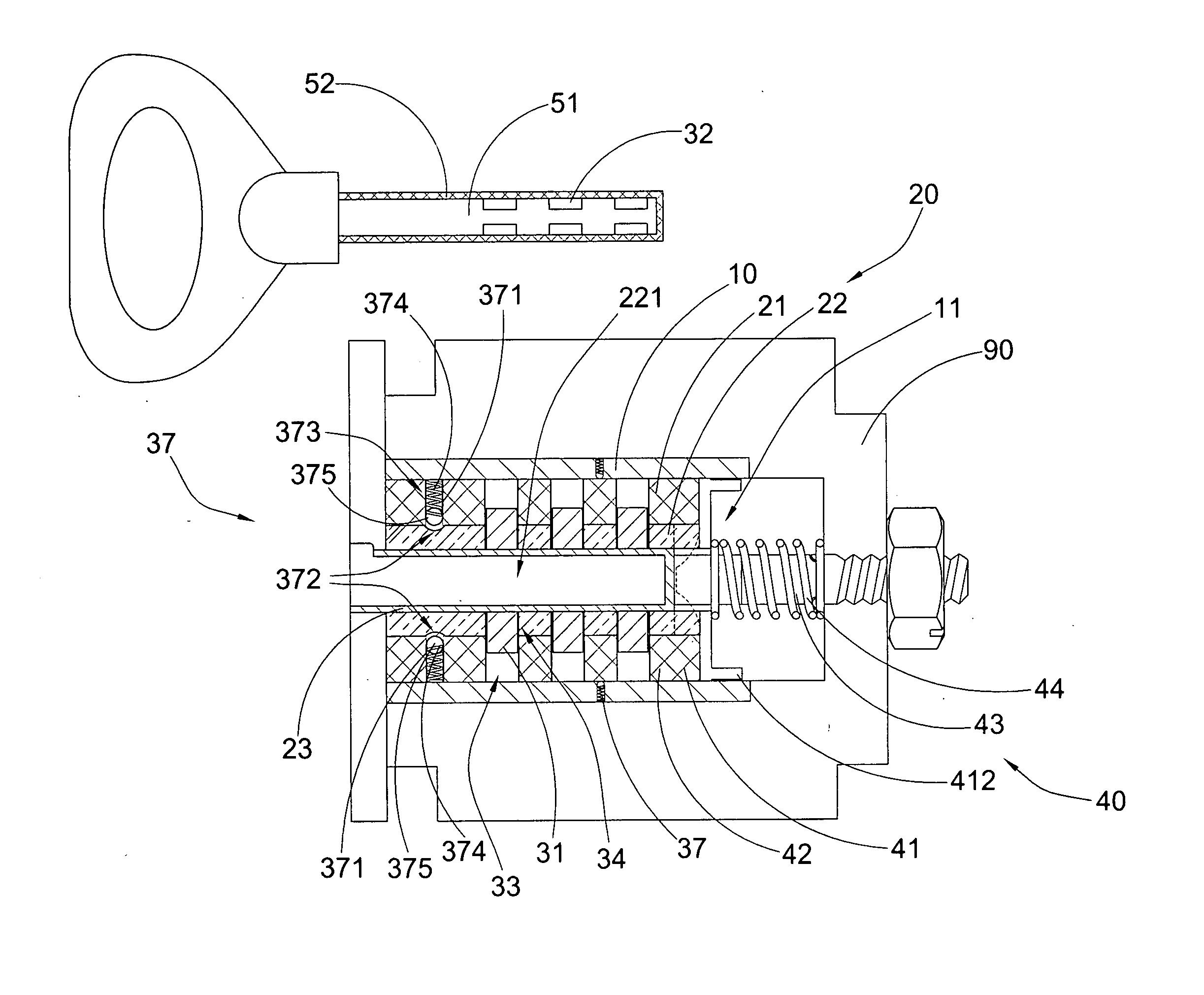
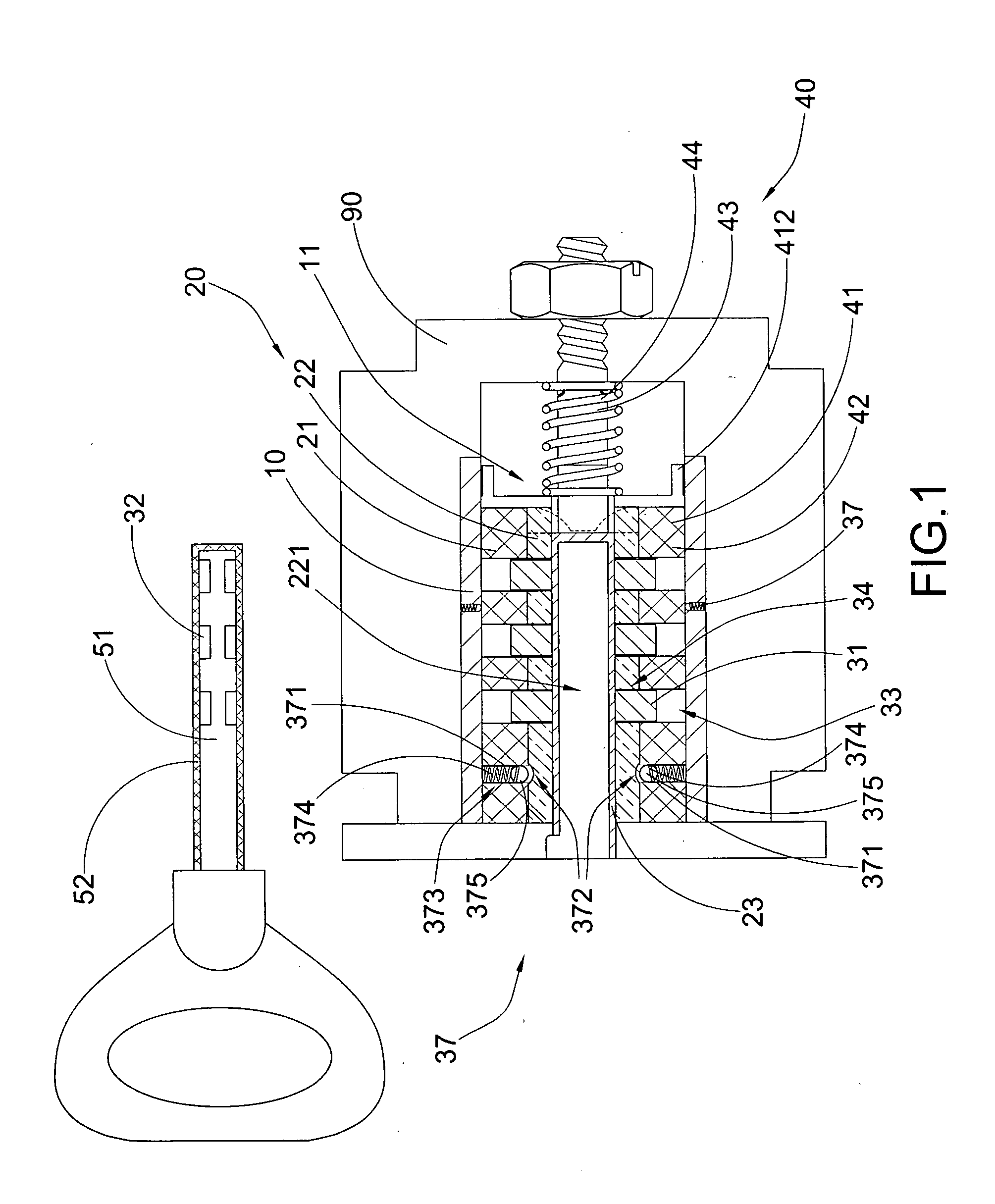
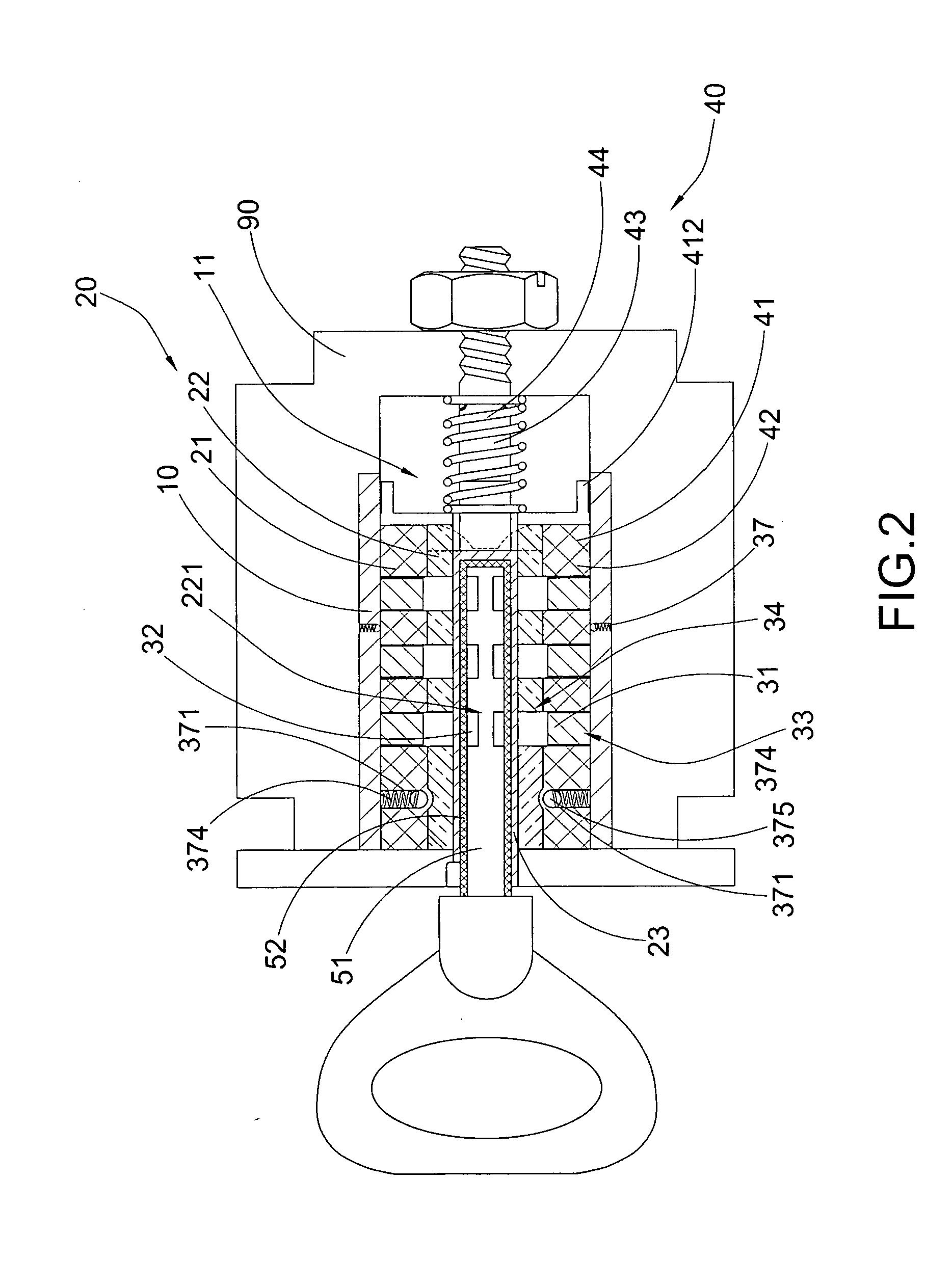
[0033]Referring to FIGS. 1 to 4 of the drawings, a magnetic lock for a latch assembly 90 according to a preferred embodiment of the present invention is illustrated, wherein the magnetic lock comprises a lock sleeve 10, a lock body 20, a lock assembly, a latch actuator 40, and an actuation key 50.

[0034]The lock sleeve 10, which is made of non-magnetic material such as brass, is arranged for coupling with the latch assembly 90, wherein the lock sleeve 10 has a lock cavity 11 defined therewithin. Accordingly, the latch assembly 90 is embodied as a fuel tank cap lock to lock at a fuel inlet of the fuel tank, wherein the latch assembly 90 has a threaded portion for rotatably coupling with threaded portion of the fuel inlet. In other words, in order to open up the fuel inlet for pumping fuel into the fuel tank, the latch assembly 90 must be actuated.

[0035]The lock body 20, which is made of non-magnetic material such as brass, is coaxially disposed in the lock cavity 11 of the lock sleeve...


PUM


Abstract

A lock includes a lock sleeve, a lock body is disposed in the lock sleeve in a free rotating manner, a lock assembly, an actuating member, and an actuation key. The lock body includes a lock rotor coaxially and rotatably disposed within the lock sleeve, and a lock core coaxially and rotatably disposed within the lock rotor and defined a keyway at the lock core. The lock assembly normally locks the lock core with the lock rotor in such a manner that the lock body is free to rotate within the lock sleeve. The actuation key is slidably inserted into the keyway of the lock core to unlock the key lock unit, wherein when the lock assembly is unlocked by the actuation key, the lock core is rotated within the lock rotor to drive the actuating member to rotate and to longitudinally move for actuating a latch assembly.

Description

BACKGROUND OF THE PRESENT INVENTION[0001]1. Field of Invention[0002]The present invention relates to lock and key, and more particularly to a magnetic lock, wherein a lock body is free to rotate within an unlock sleeve at a locked position and is engaged with the lock sleeve at a locked position in association with an actuation key.[0003]2. Description of Related Arts[0004]A conventional magnetic key lock generally comprises a sleeve coupled with a latch assembly, a lock tube disposed within the sleeve, and a magnetic arrangement for locking the lock tube with the sleeve. Accordingly, the magnetic arrangement comprises a plurality of magnetic elements radially placed at the sleeve to normally engage with the indented surfaces of the lock tube so as to lock up a rotational movement of the lock tube within the sleeve. A magnetic key is inserted into the lock tube, wherein a plurality of magnets are radially placed along the magnetic key to magnetically induct with the magnetic element...

Claims


Application Information

Patent Timeline
Patent Type & Authority Applications(United States)
IPC IPC(8): E05B27/00E05B15/00
CPCE05B15/00E05B27/0017E05B47/0044E05B17/045E05B27/0046Y10T70/7486Y10T70/7593
Inventor TSAI, LINCLONTSAI, BENNCAI, JIAN HUAPONTICELLI, JR., ROBERT
Owner TSAI LINCLON
Why Eureka
Try Eureka