Implantable flow diverter

Active Publication Date: 2014-11-20
COOK MEDICAL TECH LLC
View PDF11 Cites 9 Cited by
  • Summary
  • Abstract
  • Description
  • Claims
  • Application Information

AI Technical Summary

Benefits of technology

The patent seeks to provide an improved treatment for aneurysms, specifically an implantable flow diverter. The flow diverter is designed to divert the flow of blood from the aneurysm to reduce the pressure on its walls. The device has a panel that acts as a barrier to blood, which is placed at the base of the basilar artery to treat an aneurysm. The panel has slots or perforations that enable it to compress the device radially for deployment. The method also reduces the flow of fluid in the center of the vessel and evens the flow of fluid across its width. Overall, this improves the treatment of aneurysms by reducing the pressure on their walls and promoting blood flow in a more even manner.

Problems solved by technology

While this can be effective in the treatment of many types of aneurysm, it is less effective when the aneurysm occurs at a bifurcation or trifurcation, such as at the base of the basilar artery.
It is also known to close off the entrance to the aneurysmal sac or to divert the flow of fluid therefrom, but known devices are not general suitable for treatment of aneurysms at the base of the basilar artery.

Method used


Image

  • Implantable flow diverter
  • Implantable flow diverter
  • Implantable flow diverter

Examples


Embodiment Construction

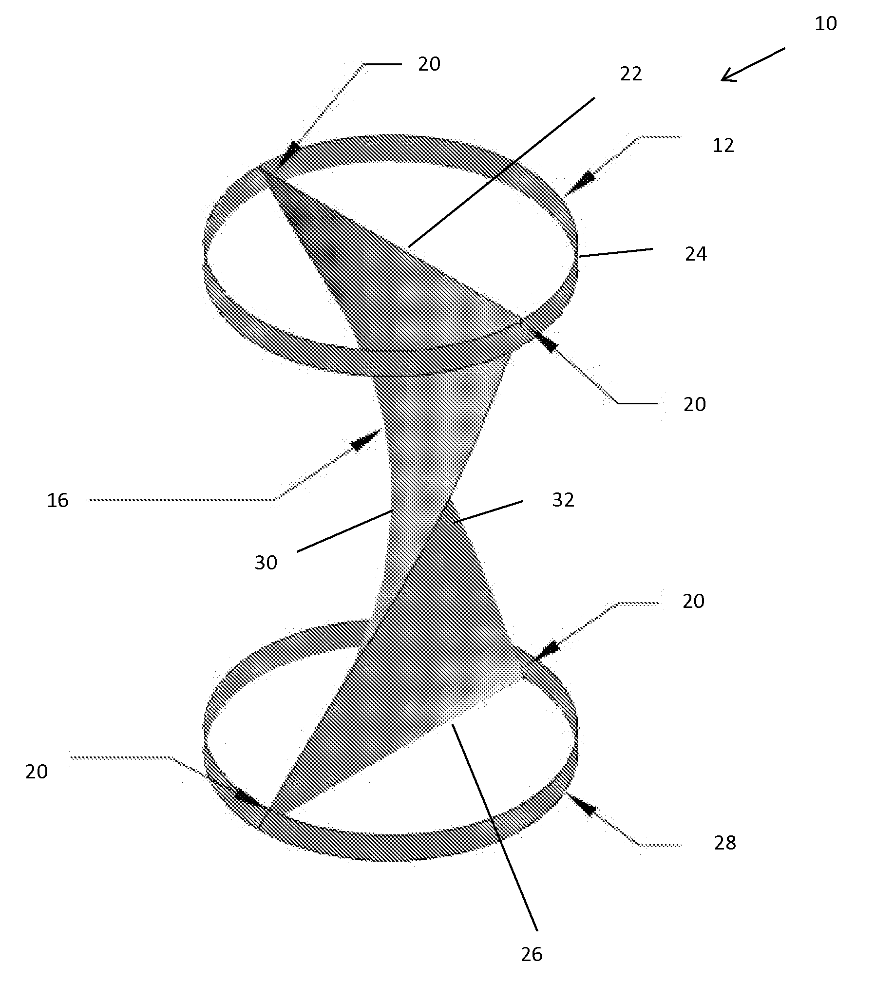
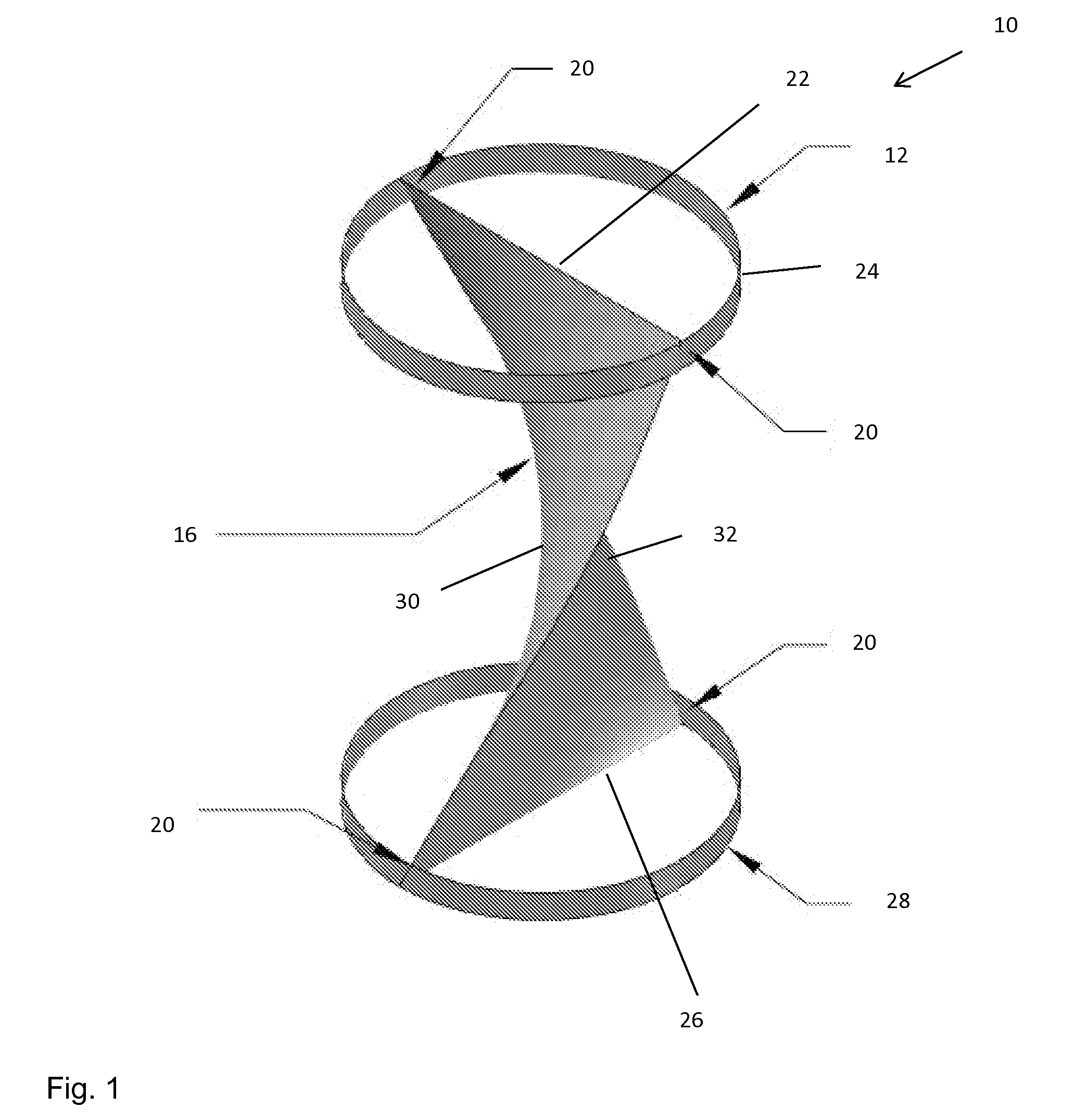
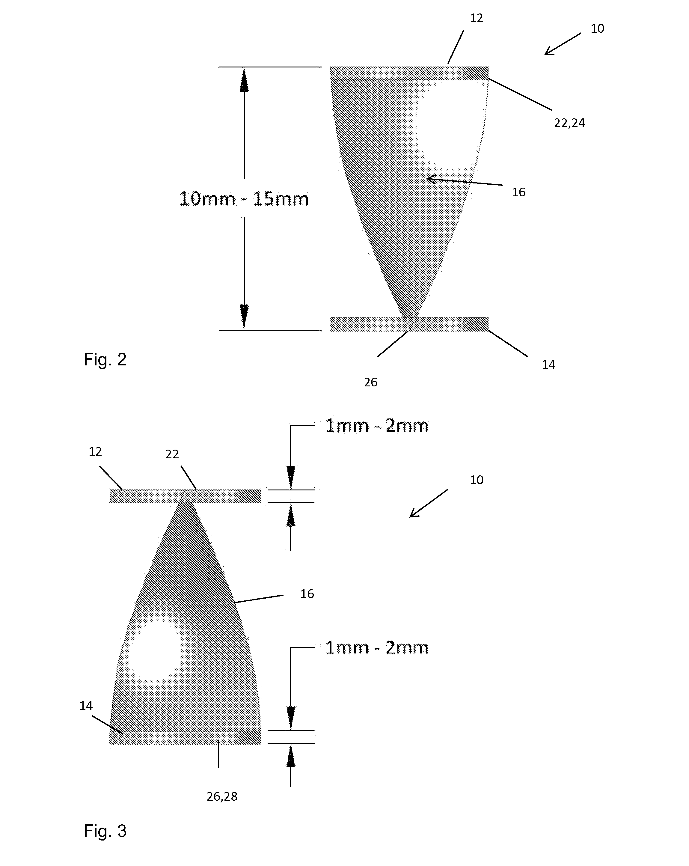
[0030]Described below are various embodiments of flow diverter for diverting flow within a patient's vessel. The term flow diverter as used herein encompasses the guiding of the flow of blood within a vessel, in particular to alter the pressure profile across the diameter of the vessel and in the preferred embodiments to reduce the pressure flow at the center of the vessel and preferably so as to even out the flow pressure across the diameter of the vessel.

[0031]As will be appreciated from the disclosure of the preferred embodiments set out below and in the accompanying drawings, these provide a flow diverter which has the same or substantially the same cross-sectional area at the proximal and distal ends of the device, that is at the inlet and outlet of the device. As a result of this, there is no change in the overall volume of fluid passing through the flow diverter and no overall change in pressure of fluid passing through the diverter. Experimental data has shown that the prefe...


PUM


Abstract

A flow diverter for implantation into a patient's vessel includes a distal annular support element and a proximal annular support element, the proximal and distal support elements supporting a longitudinally twisted diverter element. The flow diverter is designed to be disposed within a vessel and to impart a rotational or twisting motion to the flow of blood passing therethrough, thereby to reduce the pressure of blood at the center of the vessel. Such flow diversion can reduce the pressure of blood impinging upon an aneurysm at a bifurcation downstream of the vessel. The device can be particularly useful for the treatment of aneurysms occurring at the bifurcation between the basilar artery and the posterior cerebral arteries.

Description

CROSS-REFERENCE TO RELATED APPLICATIONS[0001]This application claims the benefit of priority under 35 U.S.C. §119(a) to Great Britain Patent Application No. 1308652.5, filed May 14, 2013, which is incorporated by reference here in its entirety.TECHNICAL FIELD[0002]The present disclosure relates to an implantable medical device, in particular for diverting flow within the vessel of a patient.BACKGROUND ART[0003]Many factors contribute to the formation of saccular aneurysms, particularly neural aneurysms. One of the major contributors is wall shear stress (WSS), which in addition to hypertension leads to a reduction in the elastic tissue of the tunica media, thereby contributing to the formation of the aneurysm. The effect of wall shear stress is heightened at certain anatomical geometries such as bifurcations, and for instance at the point where the basilar artery (BA) divides into the posterior cerebral arteries (PCA).[0004]It is known to try to treat aneurysms by filling the aneury...

Claims


Application Information

Patent Timeline
IPC IPC(8): A61F2/06
CPCA61F2002/068A61F2/06A61B17/12113A61B17/12145A61F2/91A61F2210/0014A61F2230/0091A61F2250/0012
Inventor FUREY, AIDAN
Owner COOK MEDICAL TECH LLC
Why Eureka
Try Eureka