Communication circuit and associated method for calibrating communication circuit

a communication circuit and associated method technology, applied in the direction of transmission monitoring, line-transmission details, receiver monitoring, etc., can solve the problems of large calibration resources, inefficient convention gain calibration, and unavoidable non-uniform power measurement accuracy of communication devices over a wide frequency range, so as to facilitate interference rejection

Active Publication Date: 2015-02-26
MEDIATEK INC
View PDF19 Cites 2 Cited by
  • Summary
  • Abstract
  • Description
  • Claims
  • Application Information

AI Technical Summary

Benefits of technology

[0011]Before and / or during demodulating the signaled calibration signal, the method may further include: performing a frequency error compensation by tuning values of the plurality of demodulation frequencies. By frequency error compensation, the method may facilitate interference rejection, because demodulation and power calculation may suppress interference(s) which occurs at frequency (or frequencies) other than the demodulation frequencies and consequently contaminate the calibration signal received by the communication circuit.

Problems solved by technology

However, communication device unavoidably suffers non-uniform power measurement accuracy over wide frequency range.
Hence, the convention gain calibration is inefficient because so many iterations consume much calibration resources, including time and cost.

Method used


Image

  • Communication circuit and associated method for calibrating communication circuit
  • Communication circuit and associated method for calibrating communication circuit
  • Communication circuit and associated method for calibrating communication circuit

Examples


Embodiment Construction

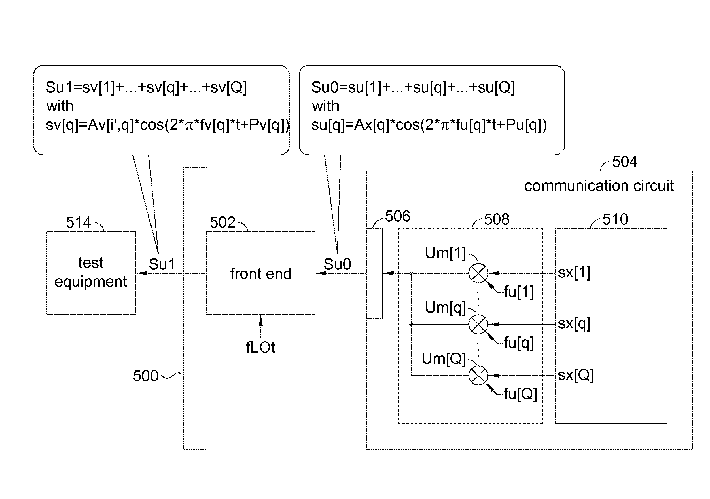
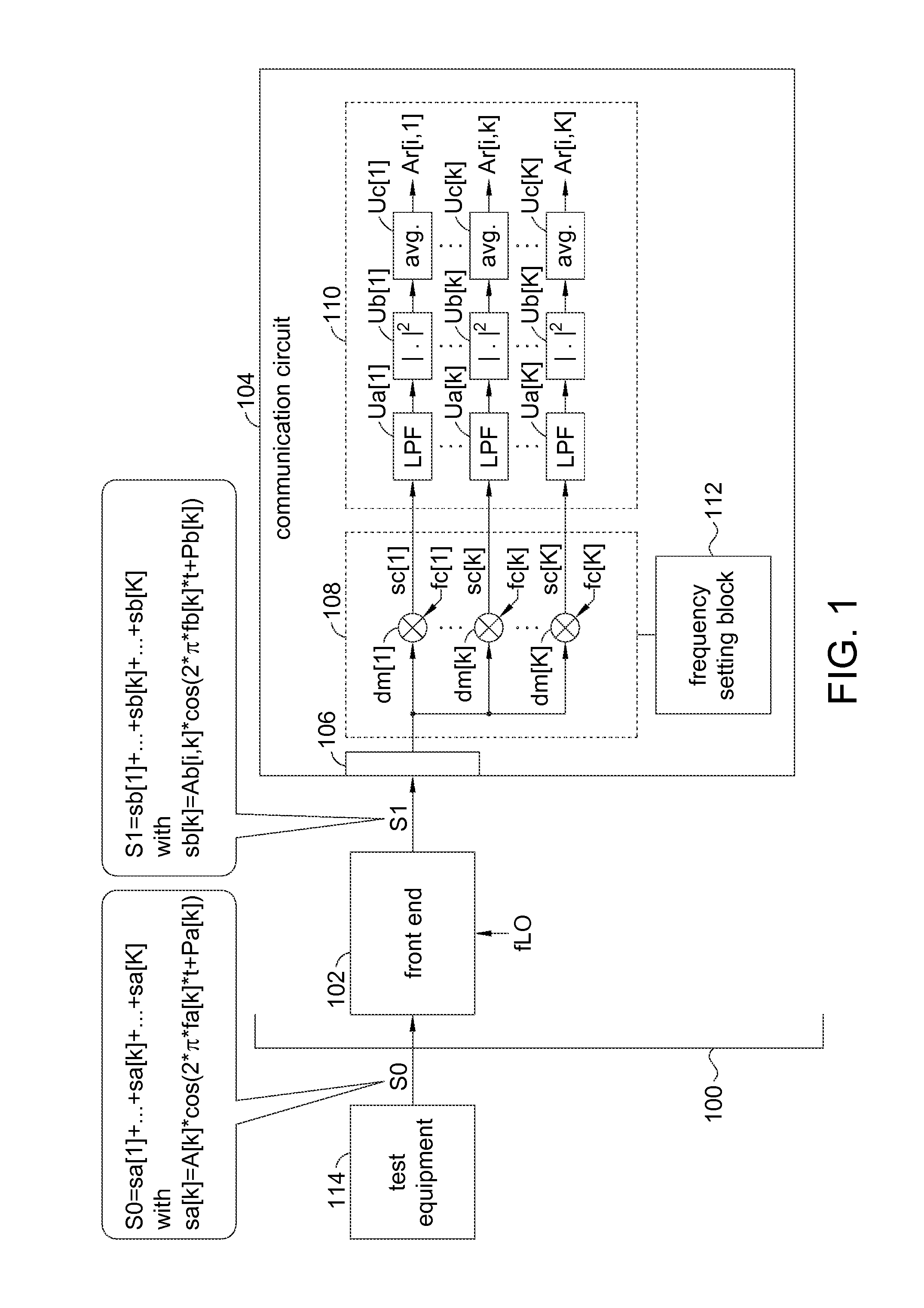
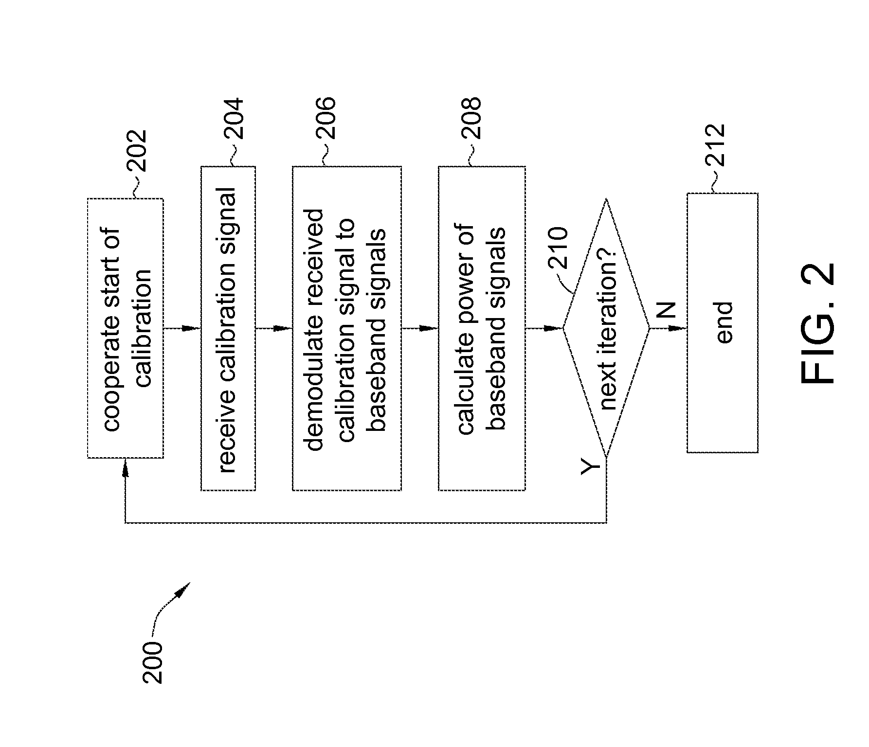
[0035]Please refer to FIG. 1 and FIG. 2, respectively illustrating a communication device 100 and a flowchart 200 according to an embodiment of the invention. The communication device 100 may include a front end 102 and a communication circuit 104, and may adopt the flowchart 200 to calibrate power measurement accuracies of the communication device 100 in cooperation with an external test equipment 114.

[0036]As shown in FIG. 1, to implement the flowchart 200 according to the invention, the test equipment 114 may be a signal source capable of synthesizing a calibration signal S0, which may include a plurality of coexisting component signals sa[1] to sa[K]. For example, each component signal sa[k] (for k=1 to K) may be a sinusoidal time varying signal expressed by A[k]*cos(2**fa[k]*t+Pa[k]), with terms A[k], fa[k] and Pa[k] respectively being an amplitude, a frequency and a phase of the component signal sa[k]. For different component signals sa[k1] and sa[k2], the frequencies fa[k1] a...


PUM


Abstract

The present invention provides a method for calibrating a communication circuit. In an embodiment, the method may include: cooperating start of a calibration procedure, and, by the communication circuit, signaling a calibration signal between a test equipment and the communication circuit. The calibration signal may include a plurality of coexisting component signals respectively at a plurality of calibration frequencies. Associated communication circuit is also disclosed.

Description

[0001]This application claims the benefit of U.S. provisional application Ser. No. 61 / 870,056, filed Aug. 26, 2013, the subject matter of which is incorporated herein by reference.FIELD OF THE INVENTION[0002]The present invention relates to communication circuit and associated method for calibrating communication circuit, and more particularly, to communication circuit and associated method for calibrating communication circuit with low time consumption, frequency error compensation, interference rejection, and / or thorough consideration of mutual influence between multiple paths of aggregate carriers.BACKGROUND OF THE INVENTION[0003]Communication devices, such as cell phones and smart phones adopting wireless 2G / 3G / 4G (LTE, long term evolution) mobile telecommunication standard(s), have become prevailing and essential for contemporary information society. To successfully establish mobile communication, communication devices need to be calibrated.[0004]For example, while a communicat...

Claims


Application Information

Patent Timeline
Patent Type & Authority Applications(United States)
IPC IPC(8): H04L27/26
CPCH04L27/2646H04B17/0085H04B17/14H04B17/21H04B17/318
Inventor LIN, YU-TESHIU, TZYUAN
Owner MEDIATEK INC
Why Eureka
Try Eureka