

Motor vehicle with a vehicle frame
a technology for motor vehicles and frame parts, applied in the field of motor vehicles, can solve the problems of increased material costs and additional weight of components, and achieve the effect of high stability
- Summary
- Abstract
- Description
- Claims
- Application Information
AI Technical Summary
Benefits of technology
Problems solved by technology
Method used
Image

Examples
Embodiment Construction
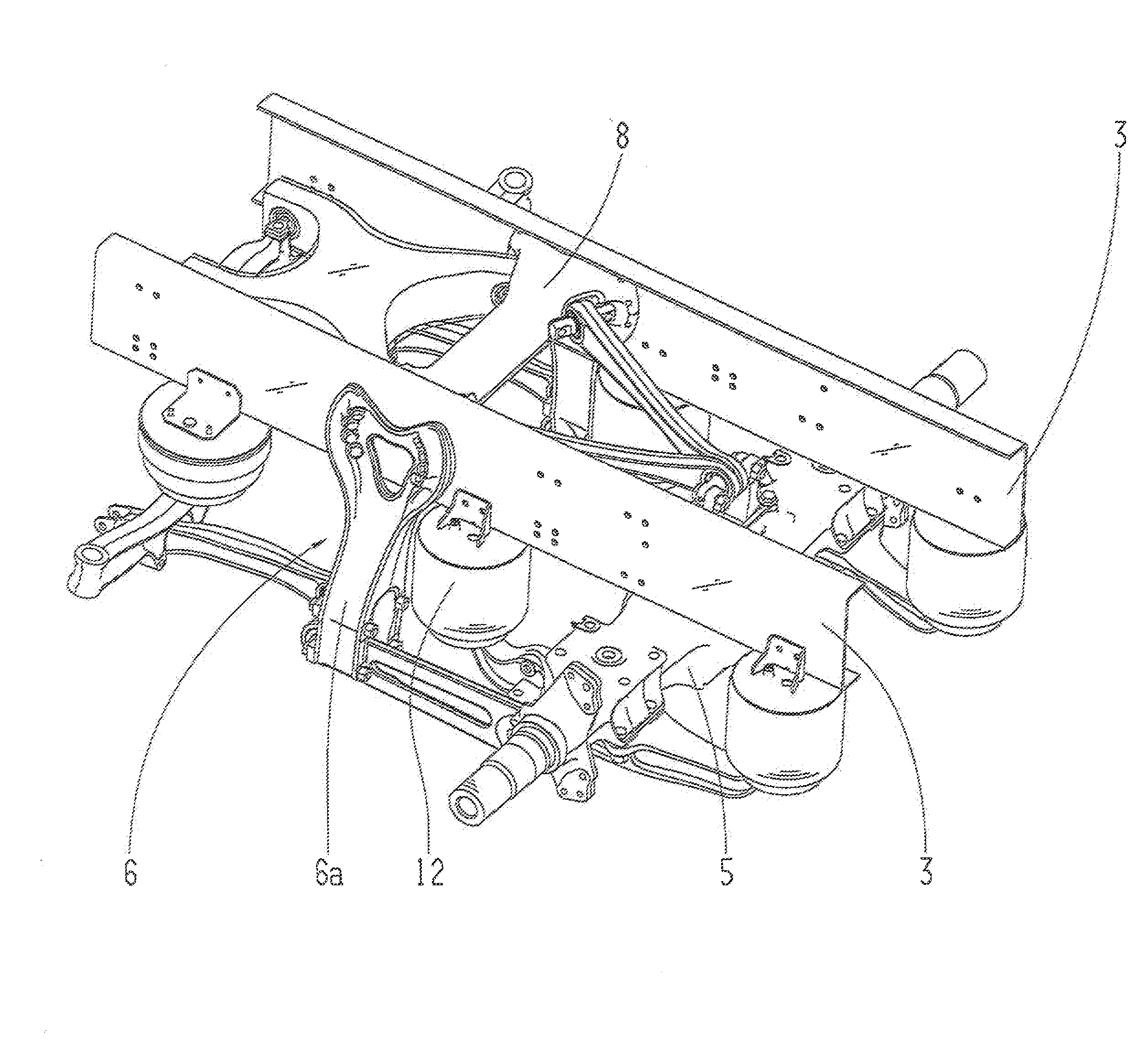
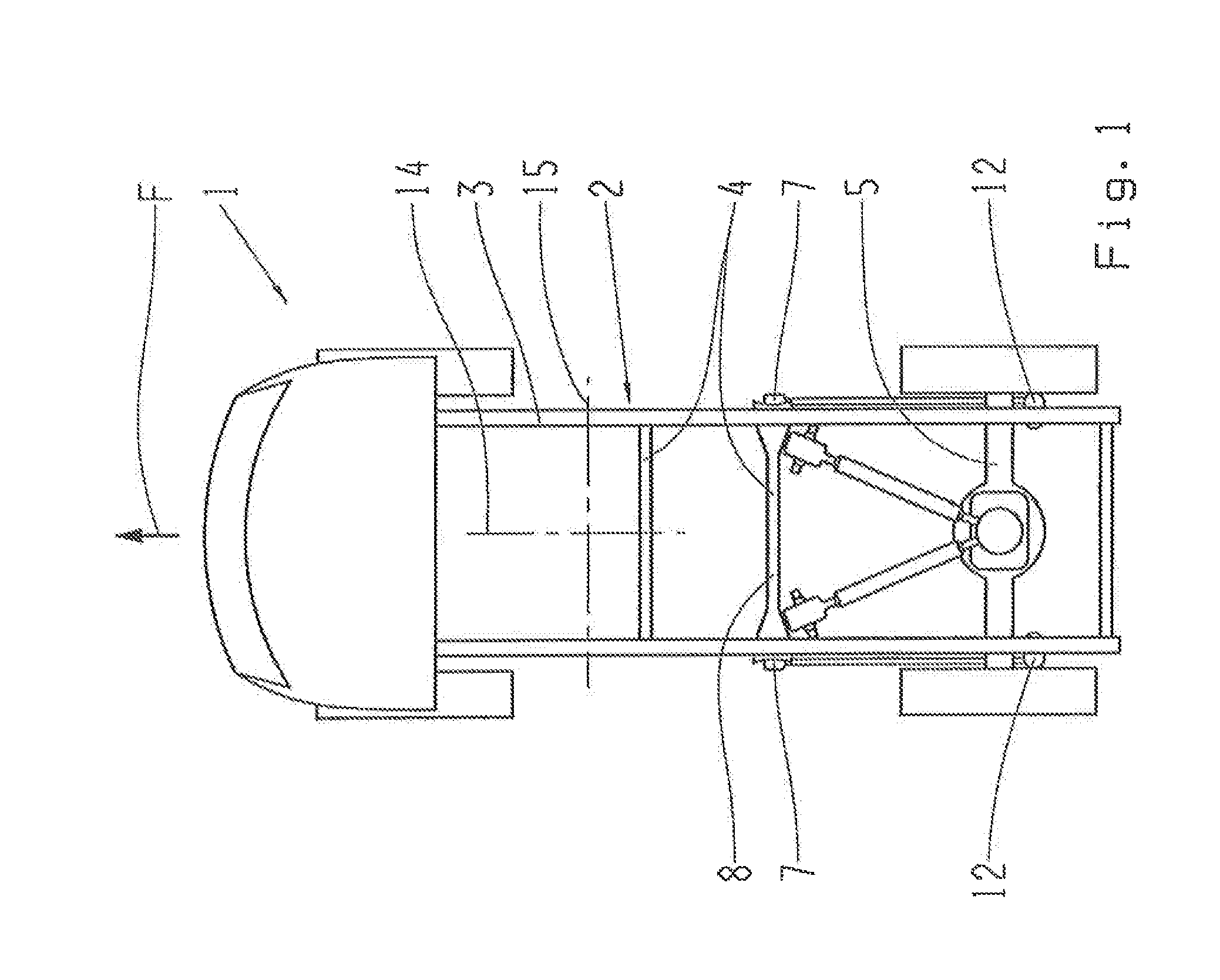
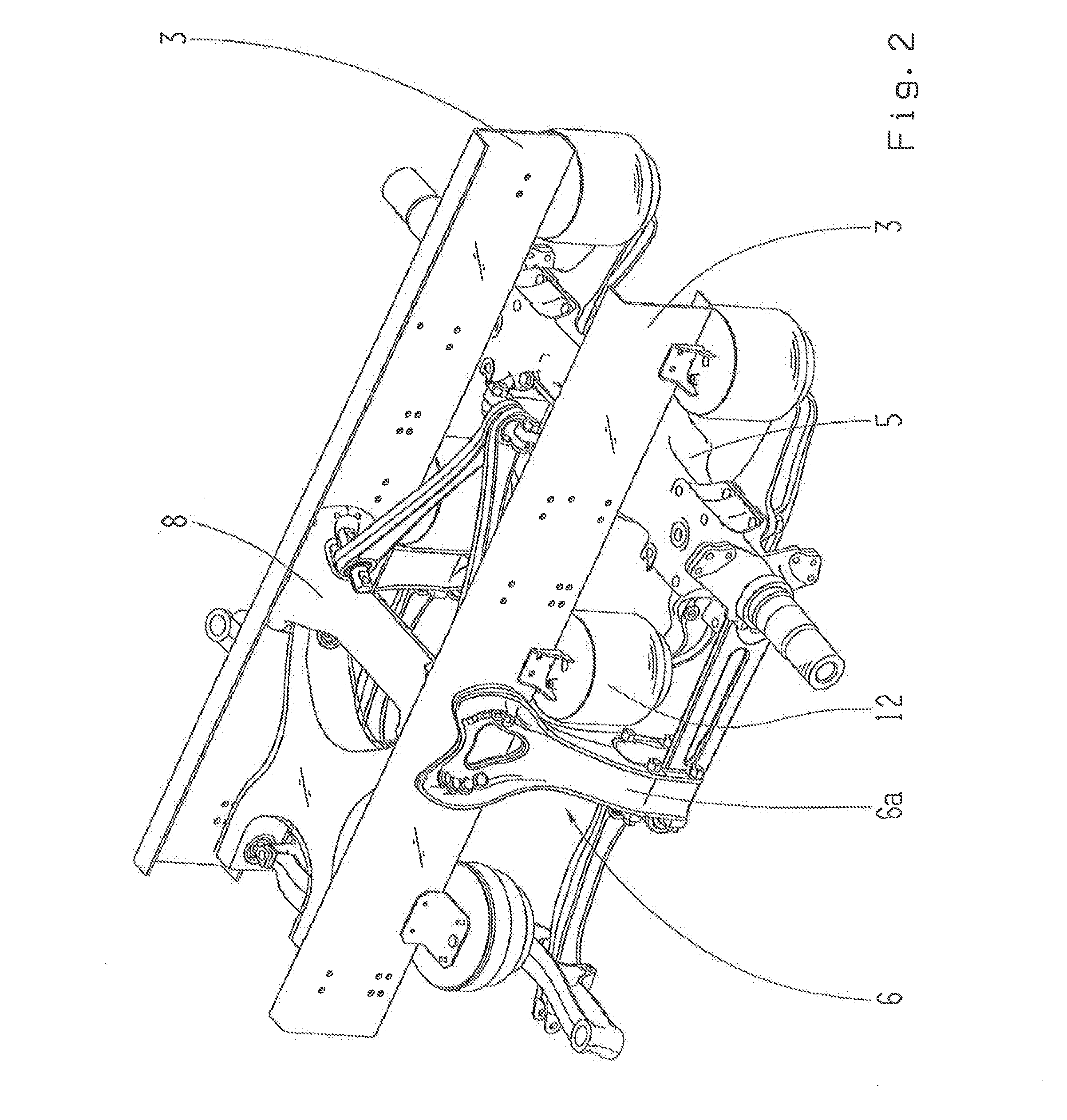
[0029]The motor vehicle 1 shown schematically in FIG. 1 is in this case a utility vehicle (UV) and comprises a vehicle frame 2 and / or a sub-frame 2a such as the air spring support shown in FIG. 8. Typically, a vehicle frame 2 can comprise two longitudinal support members 3 and a plurality of transverse support members 4, and can be variously designed as a whole. At least one axle 5, for example a rear axle, is coupled to the vehicle frame 2.
[0030]Again as examples, a building-site vehicle or an off-road vehicle can be designed in accordance with the invention.
[0031]Contact surfaces 10, 10a in particular are positioned transversely to and / or along the driving direction F, the surfaces serving as connecting surfaces on which further structural units can be fixed. For example, longitudinally extending contact surfaces 10 can be formed by the outsides or insides of the longitudinal support members 3, and transverse contact surfaces 10a for example by an extended differential of the axle...
PUM
 Abstract
Description
Claims
Application Information