Boost apparatus with over-current and over-voltage protection function

Inactive Publication Date: 2015-07-23
BEYOND INNOVATION TECH
View PDF2 Cites 12 Cited by
  • Summary
  • Abstract
  • Description
  • Claims
  • Application Information

AI Technical Summary

Benefits of technology

The invention provides a boost apparatus that can detect if the diode at the output is open-circuit and prevent damage to the system or internal components. The boost apparatus includes a boost power conversion circuit, a complex function detection circuit, and a control chip. The control chip generates a pulse-width-modulation signal to control the operation of the boost power conversion circuit and stops outputting the pulse-width-modulation signal in response to a detection signal if the first diode at the output is open-circuit or the DC output voltage is over-voltage, thereby protecting the boost apparatus and the load from damaging.

Problems solved by technology

When a diode at the output side (or output end) in the boost apparatus is open-circuit, however, the power switch on the power switching path in the boost apparatus may be damaged (short circuit, for example), which results in damaging the internal components of the boost apparatus and / or the load, or causing power short circuit and damage to the system using the boost apparatus.

Method used


Image

  • Boost apparatus with over-current and over-voltage protection function
  • Boost apparatus with over-current and over-voltage protection function

Examples


Embodiment Construction

[0019]Descriptions of the invention are given with reference to the exemplary embodiments illustrated by the drawings. In addition, wherever possible, identical or similar reference numerals stand for identical or similar elements / components in the drawings and embodiments.

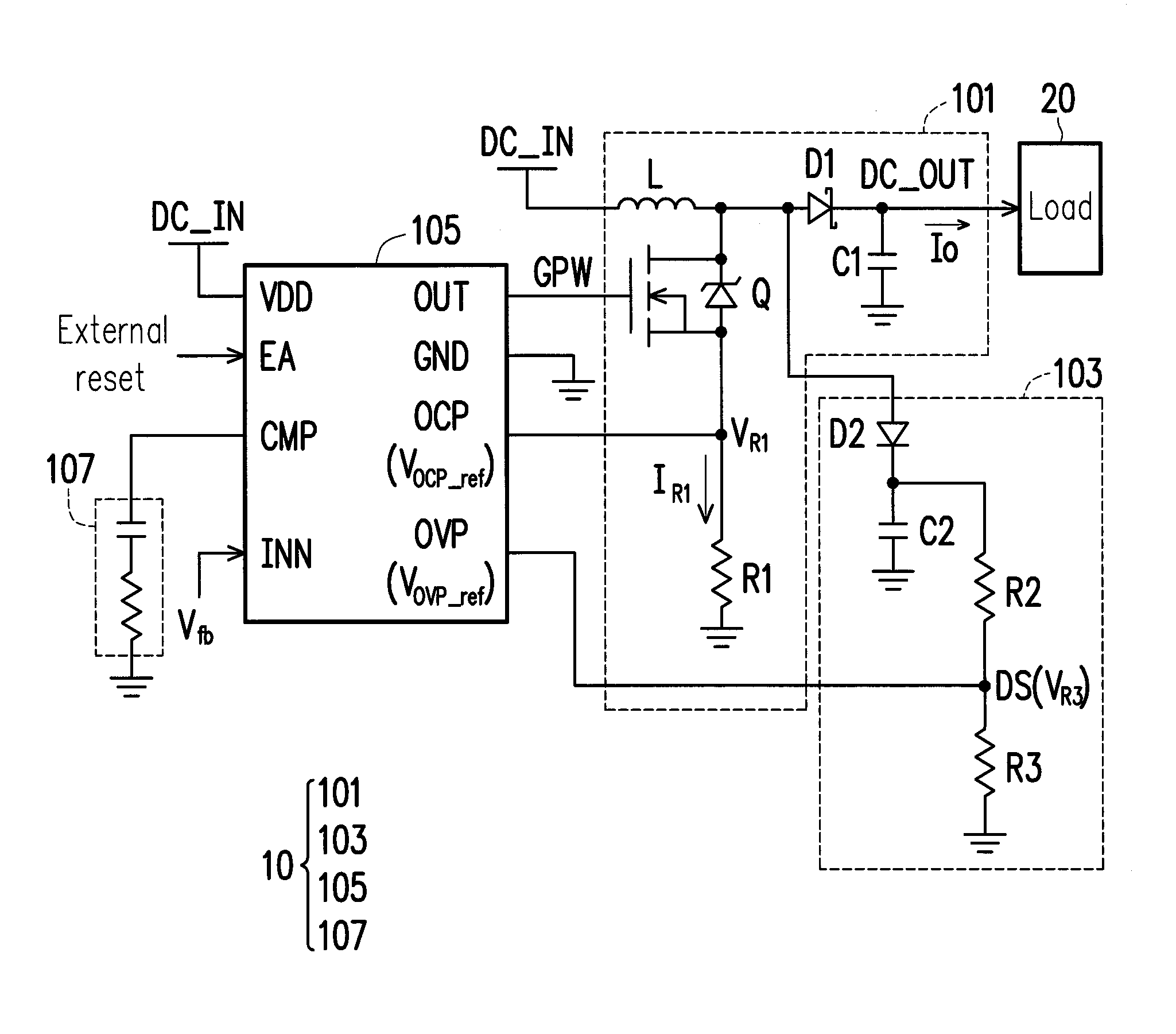
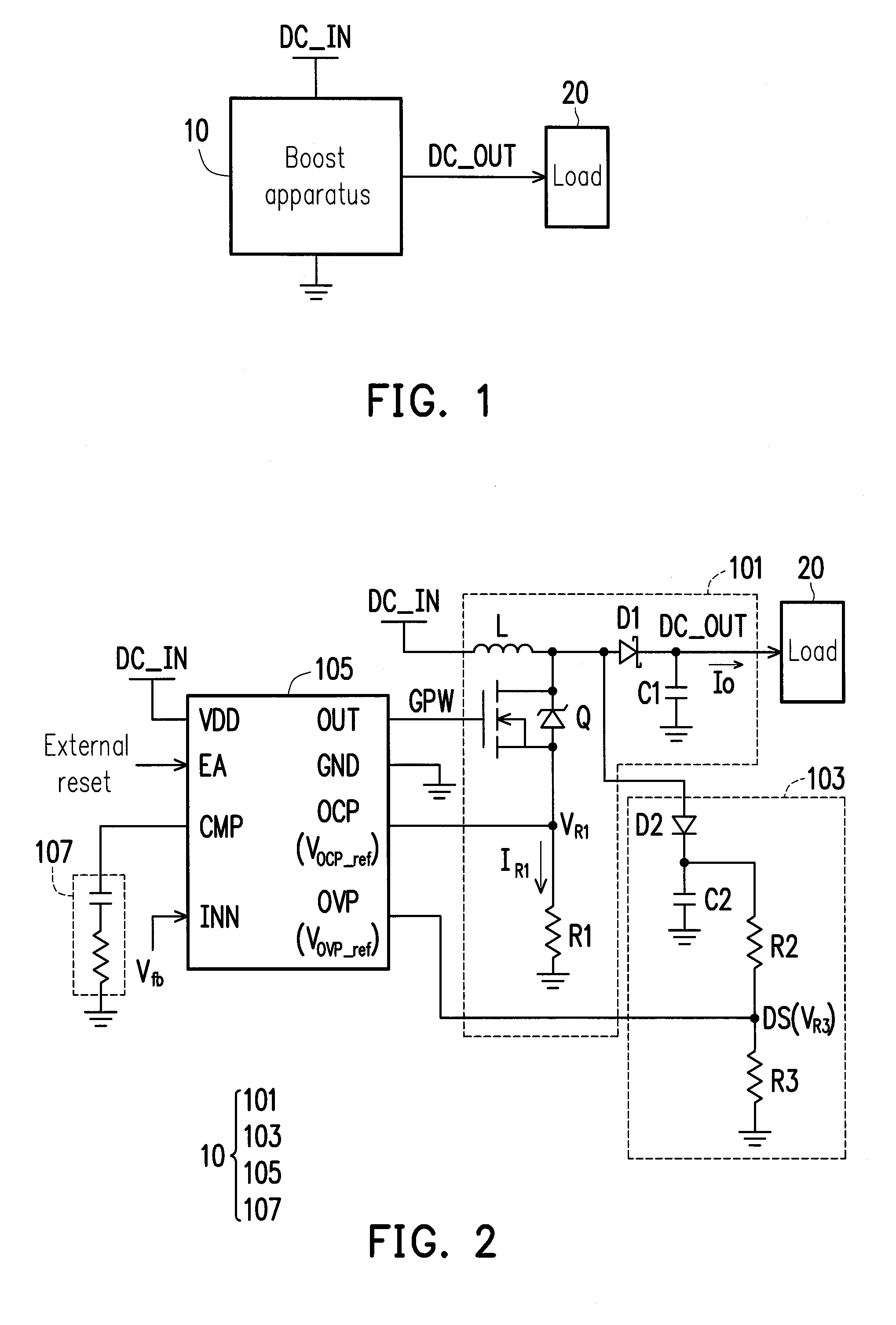
[0020]FIG. 1 is a system block diagram of a boost apparatus 10 according to an exemplary embodiment of the invention. FIG. 2 is an implementation diagram of the boost apparatus 10 in FIG. 1. With reference to FIG. 1 and FIG. 2, the boost apparatus 10 is adapted for providing a DC output voltage DC_OUT to a load 20 of any type. The boost apparatus 10 includes: a boost power conversion circuit 101, a complex function detection circuit 103, a control chip 105, and a resistor-capacitor (RC) network 107.

[0021]In this exemplary embodiment, the boost power conversion circuit 101 is configured to receive a DC input voltage DC_IN and provide the DC output voltage DC_OUT to the load 20 in response to a pulse-width-modulatio...


PUM


Abstract

A boost apparatus includes: a boost power conversion circuit having a first diode coupled to a load, and configured to receive a DC input voltage and provide a DC output voltage to the load in response to a pulse-width-modulation (PWM) signal; a complex function detection circuit coupled to an anode of the first diode and configured to detect whether the DC output voltage is over-voltage and detect whether the first diode is open-circuit and accordingly provide a detection signal; and a control chip configured to: generate the PWM signal to control the operation of the boost power conversion circuit; and stop outputting the PWM signal and enter a shutdown status in response to the detection signal when the first diode is open-circuit or the DC output voltage is over-voltage, thereby protecting the boost apparatus and / or the load from damaging.

Description

CROSS-REFERENCE TO RELATED APPLICATION[0001]This application claims the priority benefits of Taiwan application serial no. 103101773, filed on Jan. 17, 2014 and Taiwan application serial no. 103131540, filed on Sep. 12, 2014. The entirety of each of the above-mentioned patent applications is hereby incorporated by reference herein and made a part of this specification.BACKGROUND OF THE INVENTION[0002]1. Field of the Invention[0003]The invention relates to power conversion and supply technology and more particularly relates to a boost apparatus having over-current and over-voltage protection functions.[0004]2. Description of Related Art[0005]The current PWM-based boost apparatus may be configured to provide DC output voltage to the load. When a diode at the output side (or output end) in the boost apparatus is open-circuit, however, the power switch on the power switching path in the boost apparatus may be damaged (short circuit, for example), which results in damaging the internal c...

Claims


Application Information

Patent Timeline
IPC IPC(8): H02H3/00H02H7/12H02M3/156H02M1/36
CPCH02H3/00H02M3/156H02H7/1213H02M1/36H02H3/202H02M1/32
Inventor LIN, CHIU-YUANLEE, MING-CHANGHUNG, CHIEN-PANG
Owner BEYOND INNOVATION TECH
Why Eureka
Try Eureka