Photographic lighting system for tactile tablet

a technology of lighting system and tactile tablet, which is applied in the field of photographic lighting system for tactile tablet, can solve the problems of no photographic flash suitable for being added, no tablet marketed on the date, and present application equipped with photographic flash, etc., and achieves the effect of convenient handling, transportation and storag

a technology of lighting system and tactile tablet, which is applied in the field of photographic lighting system for tactile tablet, can solve the problems of no photographic flash suitable for being added, no tablet marketed on the date, and present application equipped with photographic flash, etc., and achieves the effect of convenient handling, transportation and storag

US20150207963A1Inactive Publication Date: 2015-07-23ACEP FRANCE

Image

  • Photographic lighting system for tactile tablet
  • Photographic lighting system for tactile tablet
  • Photographic lighting system for tactile tablet

Examples


Embodiment Construction

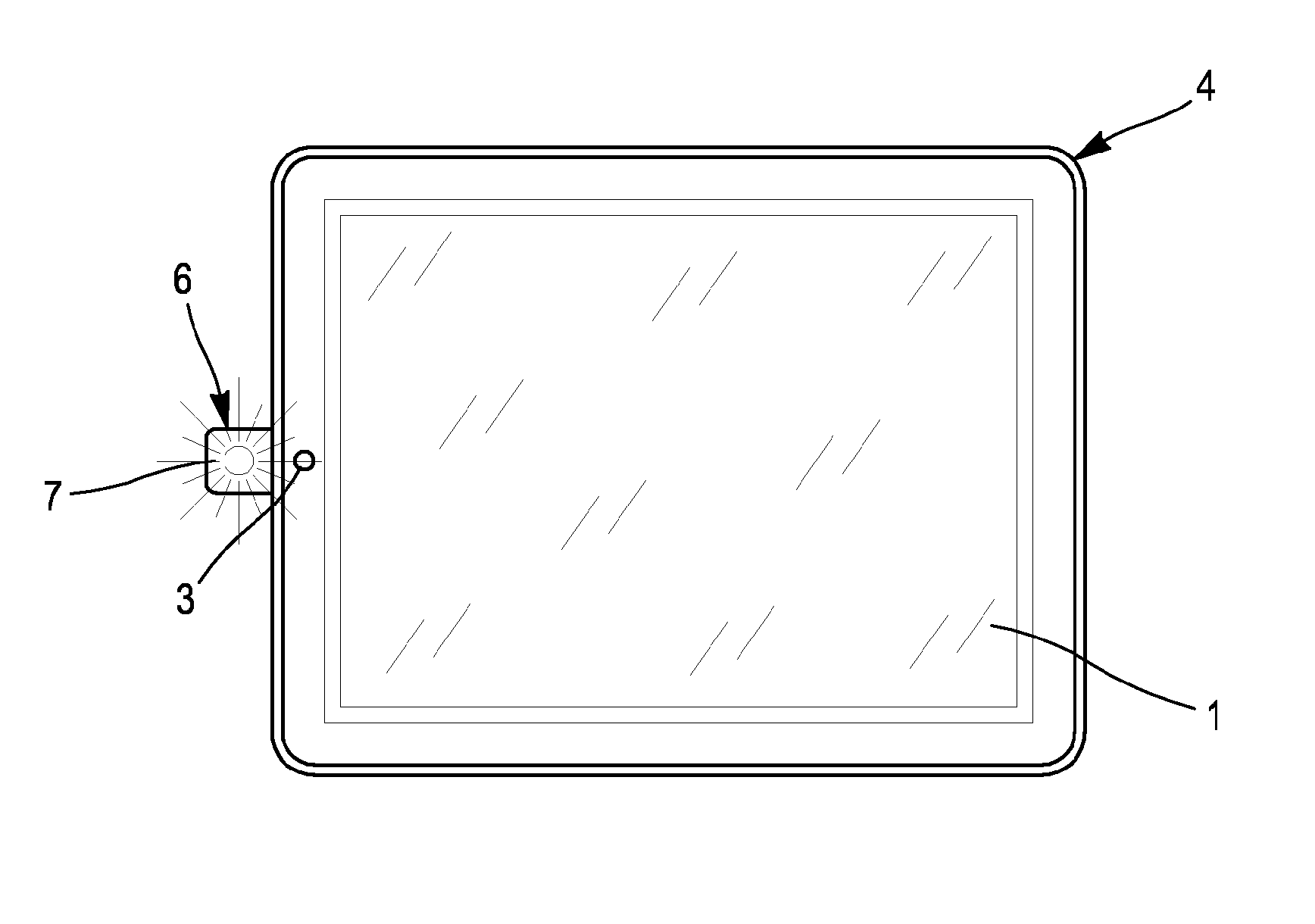
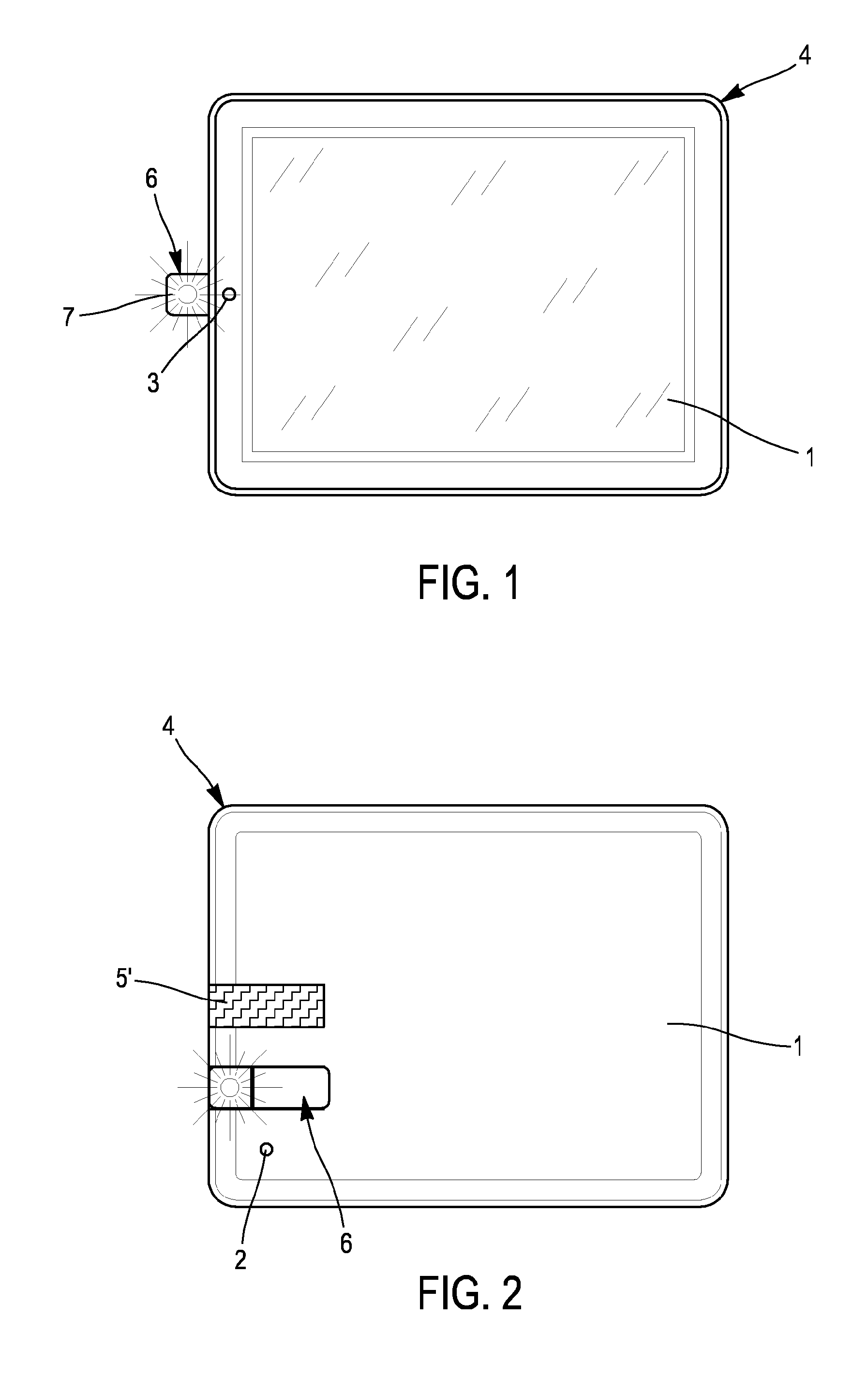
[0020]With reference to FIGS. 1 and 2, a tactile tablet 1 is shown comprising a first back camera 2 and a second front camera 3. A touch screen occupies almost all of the front face thereof. This tablet is equipped with a photographic lighting system according to the present invention.

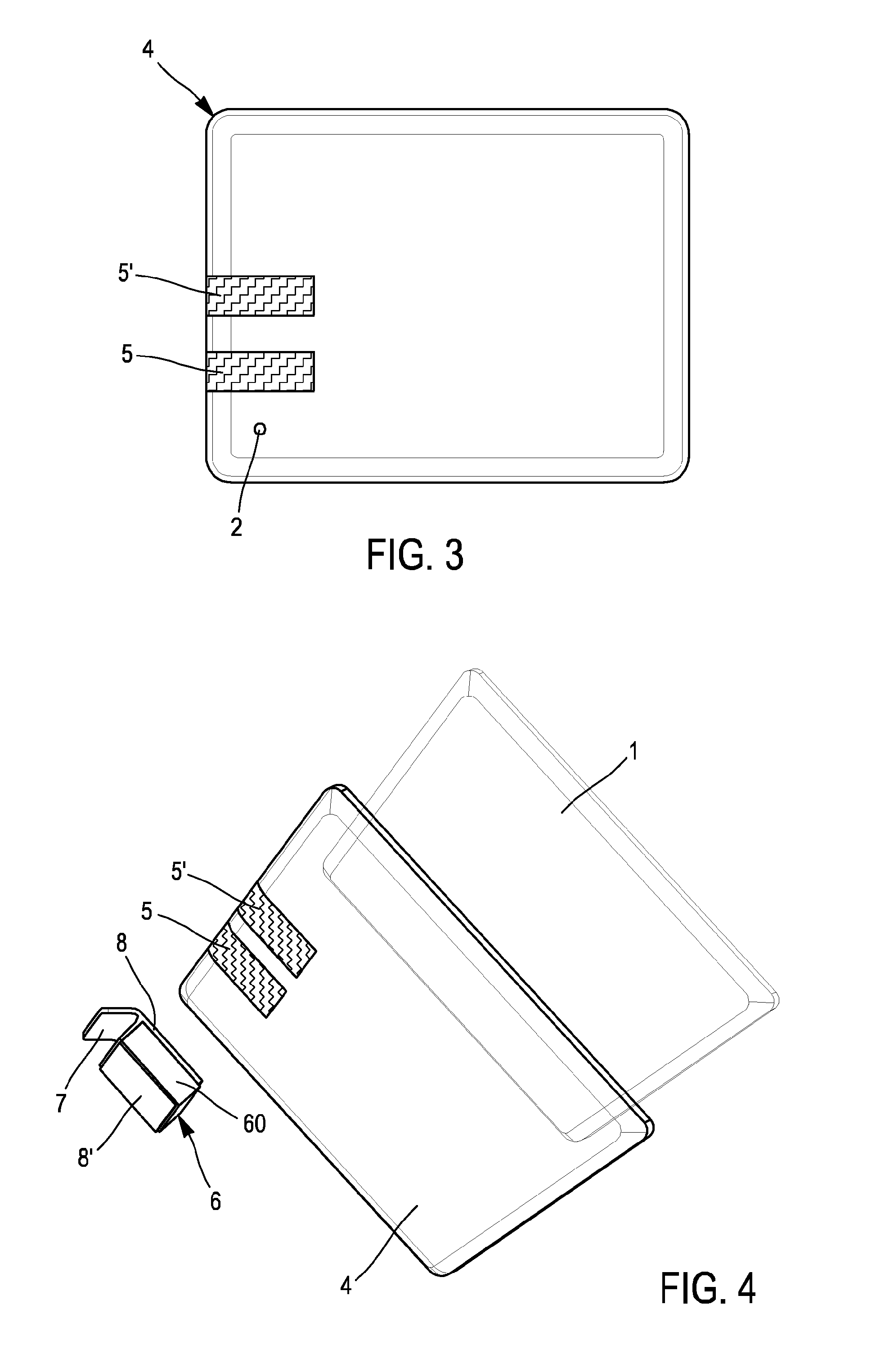
[0021]According to one essential feature, said system consists of a removable protective back shell 4 and a light source 6.

[0022]According to the alternative embodiment shown, the shell 4 and the light source 6 are furnished with connection means enabling removable fixing of the light source 6 to said shell 4.

[0023]According to a further alternative embodiment, not shown in the figures, the light source 6 is fixed directly to the shell 4, permanently. In this embodiment, the light source 6 is advantageously a light-emitting diode, equipped with a power supply cable. Preferably, the diode is of the SMC (Surface-Mounted Component) type. Indeed, thus having very small dimensions, particularly in respect o...


PUM


Abstract

The present invention relates to a photographic lighting system for tactile tablet including a first dorsal camera noteworthy in that said system can have a removable dorsal protective shell and a light source. According to a variant, the shell and the light source are furnished with connection capabilities allowing removable fixing of the light source to said shell. Preferably, the connection means are magnets. Preferred use in connection with a measurement capture computer program for the optical centring of lenses in a spectacles frame as a function of the physiognomy of the wearer of said frames and of the characteristics of said frames.

Description

FIELD OF THE INVENTION[0001]The present invention relates to a photographic lighting system for a tactile tablet.PRIOR ART[0002]The term tactile tablet denotes herein an ultra-flat portable computer, in the form of a touch screen and which is particularly suitable for accessing multimedia content.[0003]In the field of vision correction spectacles, measurements are made on the wearer fitted with spectacle frames chosen by the wearer to determine data relating to the layout configuration of the corrective lenses, particularly the optical centring thereof, opposite the wearer's eyes. These data are essentially the pupillary distance, the pupillary height, the frame inclination and curvature, the pantoscopic angle, the lens-eye distance.[0004]To make these measurements, a series of mechanical instruments exist operated in succession by an optician trained for this purpose in order to obtain the data required. This technique requires however a certain time and requires certain know-how o...

Claims


Application Information

Patent Timeline
23 Jul 2015
Publication
US20150207963A1
IPC
H04N5/225; G06F3/01; G03B15/05
CPC
H04N5/2251; G03B15/05; G03B2215/0582; H04N5/2256; G06F3/016; H04M1/724092; G03B15/03; H04B1/3888
Inventors
SAYAG, JEAN-PHILIPPE