Percutaneous exchange tube and method of use

Active Publication Date: 2015-09-24
OSTEOMED
View PDF6 Cites 27 Cited by
  • Summary
  • Abstract
  • Description
  • Claims
  • Application Information

AI Technical Summary

Benefits of technology

[0004]The present invention provides for an apparatus and a medical procedure used to install a cannulated screw or other fastener which does n

Problems solved by technology

However, these small wires are very difficult to position due to their small diameter.
Larger wires cannot be u

Method used


Image

  • Percutaneous exchange tube and method of use
  • Percutaneous exchange tube and method of use
  • Percutaneous exchange tube and method of use

Examples


Embodiment Construction

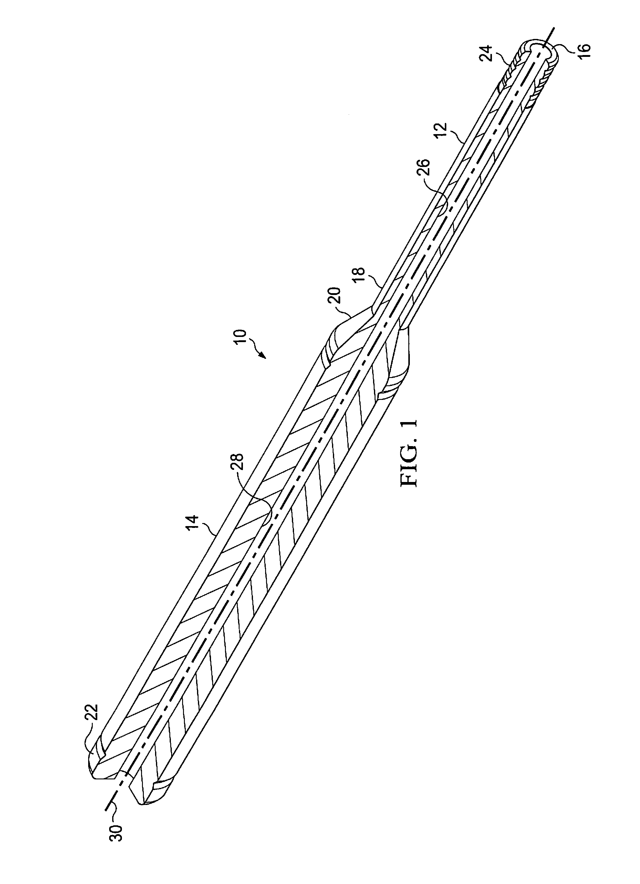
[0014]Referring to FIG. 1, the apparatus of the present invention, also referred to as a percutaneous exchange tube 10 or exchange tube 10, comprises a first portion 12 and a second portion 14. First portion 12 includes a first end 16 and a second end 18, and second portion 14 includes a first end 20 and a second end 22. First portion 12 is attached or connected to second portion 14. Second portion 14 has a slightly larger outer diameter, permitting the surgeon to more easily grasp the instrument. First end 16 of portion 12 has a threaded portion 24. First portion 12 and second portion 14 each include a hollow elongated section 26 and 28, respectively, which extend along the longitudinal axis 30 of first portion 12 and second portion 14. Once manufactured as a single unit or first and second portions 12 and 14 are attached in a permanent manner, hollow section 26 is coaxially aligned with hollow section 28, providing a uniform inner diameter.

[0015]Exchange tube 10 is intended to be ...


PUM


Abstract

An improved medical device tube is disclosed for use in a percutaneous procedure. An improved medical procedure is also disclosed to insert a cannulated screw across a fracture of a human bone using the improved tube.

Description

TECHNICAL FIELD[0001]The present disclosure relates generally to a medical device used in a percutaneous manner and the related medical procedure.BACKGROUND[0002]In the installation of cannulated screws and other fasteners in the medical field, the traditional process has been to first identify the target area into which the cannulated screw or other fastener needs to be attached. Once the target area is defined, a guide wire is implanted. Such a guide wire may be a K-wire or equivalent guide wire well known to those skilled in the art. It may be threaded at one end for rotational installation or may be inserted following the drilling of a small pilot hole. Once the preliminary guide wire is installed, a hollow drill bit is placed over the guide wire and drilled into the target area of the bone. The drill is then removed and a cannulated screw placed over the remaining guide wire. The cannulated screw is then rotated into the bone to achieve its intended purpose. Once installed, the...

Claims


Application Information

Patent Timeline
IPC IPC(8): A61B17/88
CPCA61B17/8872A61B17/1615A61B17/1686A61B17/864A61B17/8875A61B17/8897A61B2090/062A61B17/1782A61B17/88A61B17/17A61B17/1739A61B2017/349A61B17/3472A61B17/56A61B2017/564A61B17/90
Inventor VIOLA, RANDALL W.
Owner OSTEOMED
Why Eureka
Try Eureka