Clutch mechanism

a technology of clutch mechanism and clutch, which is applied in the direction of friction clutch, non-mechanical actuated clutch, clutch, etc., can solve the problems of large power consumption, achieve the effect of reducing the amount of permanent magnet to be used, reducing the magnetic flux flowing in the attracting magnetic circuit, and reducing the physical size of the permanent magn

Inactive Publication Date: 2015-10-22
DENSO CORP
View PDF3 Cites 3 Cited by
  • Summary
  • Abstract
  • Description
  • Claims
  • Application Information

AI Technical Summary

Benefits of technology

[0028]The present disclosure has been made in consideration of the above-mentioned circumstances, and an object of the present disclosure is to provide a clutch mechanism of which the physical size can be reduced with a small amount of a permanent magnet to be used and of which the power consumption of an electromagnetic coil can also be reduced.
[0035]When the cross-sectional area of the electromagnetic coil is increased and a magnetomotive force is also reduced as described above, the power consumption of the electromagnetic coil can be significantly reduced. Accordingly, while the same transmission torque as that in the related art is achieved with a small amount of the permanent magnet to be used, the physical size of the clutch mechanism can be reduced and the power consumption of the electromagnetic coil can also be reduced.

Problems solved by technology

For this reason, there is a practical problem in that a large amount of power, though momentarily, needs to be supplied to the first and second coil portions to move the movable member.

Method used


Image

  • Clutch mechanism
  • Clutch mechanism
  • Clutch mechanism

Examples


first embodiment

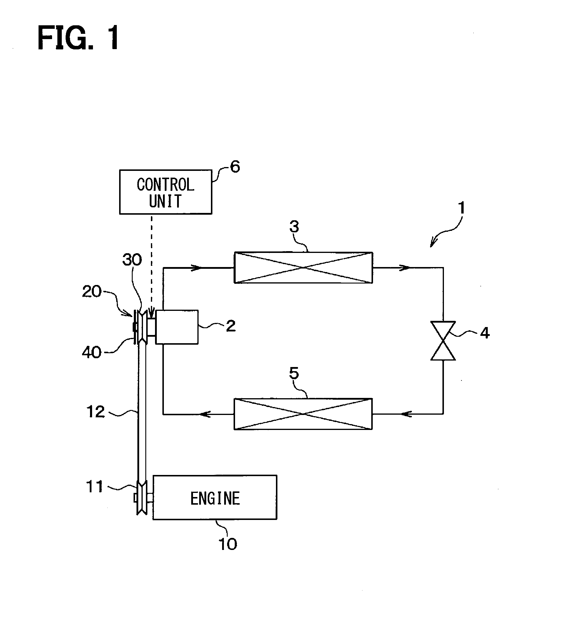
[0049]FIG. 1 is a view showing the entire configuration of a refrigeration cycle device 1 of a vehicle air conditioning apparatus to which a clutch mechanism 20 of this embodiment is applied.

[0050]The refrigeration cycle device 1 includes a compressor 2, a radiator 3, an expansion valve 4, and an evaporator 5 that are connected to each other. The compressor 2 sucks a refrigerant and compresses the refrigerant. The radiator 3 allows the refrigerant, which is discharged from the compressor 2, to radiate heat. The expansion valve 4 depressurizes and expands the refrigerant that flows out of the radiator 3. The evaporator 5 exhibits a heat absorbing action by evaporating the refrigerant that has been depressurized by the expansion valve 4.

[0051]The compressor 2 is installed in an engine room of a vehicle. The compressor 2 drives a compression mechanism by a rotational drive force, which is applied from an engine 10 as a propulsion drive source through the clutch mechanism 20, to suck a ...

second embodiment

[0144]An example in which the number of poles of the attracting magnetic circuit MCa is made to be 6 by the non-magnetic portions 90 and 91 of the armature 40 and the non-magnetic portions 70, 71, and 72 of the pulley 30 has been described in the first embodiment. However, instead of this example, an example in which an armature 40 and a pulley 30 are formed so that the number of poles of an attracting magnetic circuit MCa is 8 will be described in this embodiment.

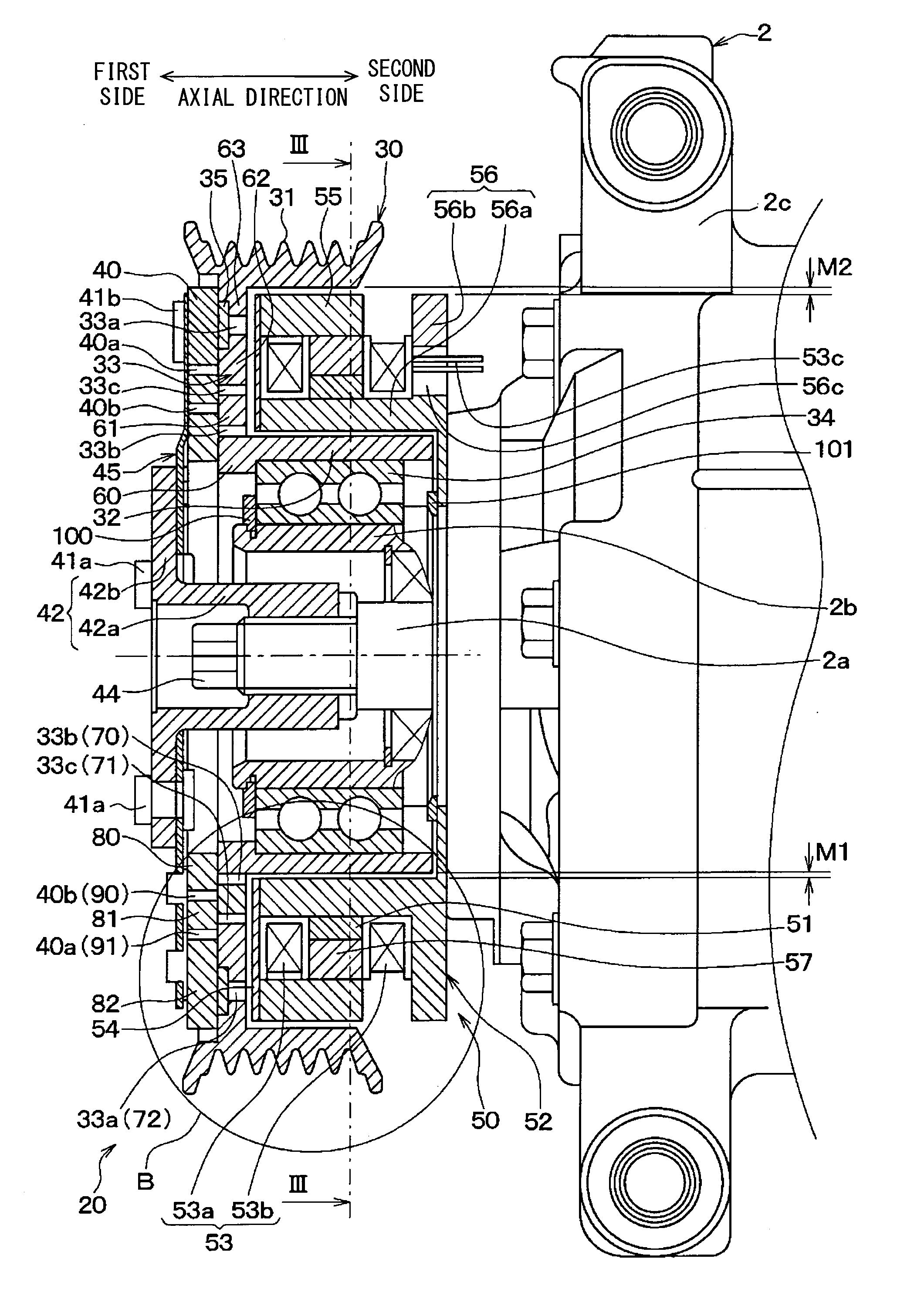
[0145]FIG. 9 is a partial cross-sectional view of a clutch mechanism 20 of this embodiment. FIG. 9 is a view corresponding to the portion B of FIG. 2.

[0146]The armature 40 of this embodiment is obtained by adding a ring member 83 and a non-magnetic portion 92 (a driven-side non-magnetic portion) to the armature 40 of the first embodiment. For this reason, the armature 40 of this embodiment includes the ring members 80, 81, 82, and 83 and the non-magnetic portions 90, 91, and 92. The ring member 83 is made of a magnetic mat...


PUM


Abstract

In a clutch mechanism, non-magnetic portions of an armature and non-magnetic portions of a pulley are offset from one another in a radial direction of a rotating shaft. For this reason, in an attracting magnetic circuit, magnetic flux passes between an outer cylindrical portion and an inner cylindrical portion so as to avoid the non-magnetic portions of the armature and the non-magnetic portions of the pulley. Accordingly, magnetic flux passes through a boundary between the armature and the pulley six times. The number of poles of the attracting magnetic circuit is increased. The physical size of a permanent magnet can be reduced. For this reason, the physical size of the clutch mechanism is reduced. As a result, the power consumption of an electromagnetic coil can be reduced by increasing the cross-sectional areas of coil portions. The physical size of the clutch mechanism is reduced and the power consumed is reduced.

Description

CROSS-REFERENCE TO RELATED APPLICATION[0001]The present application is based on Japanese Patent Application No. 2012-252465 filed on Nov. 16, 2012, the content of which is incorporated herein by reference.TECHNICAL FIELD[0002]The present disclosure relates to a clutch mechanism that uses a permanent magnet.BACKGROUND ART[0003]As an electromagnet type clutch mechanism that is widely sold in the market at present, there is a clutch mechanism that includes a pulley rotated by a rotational drive force transmitted from an engine and an armature transmitting the rotational drive force to a compressor. Such a clutch mechanism is adapted not to use a permanent magnet and is adapted to generate magnetic attraction, which causes the pulley to be attracted to the armature, from an electromagnetic coil.[0004]When the pulley and the armature are connected to each other in the clutch mechanism, the rotational drive force applied from the engine is transmitted to the compressor through the pulley ...

Claims


Application Information

Patent Timeline
Patent Type & Authority Applications(United States)
IPC IPC(8): F16D27/112F16D13/76F16D27/14F16D27/00
CPCF16D27/112F16D27/004F16D2027/008F16D27/14F16D13/76
Inventor UEDA, MOTOHIKOYAMAGAMI, YOUSUKE
Owner DENSO CORP
Why Eureka
Try Eureka