

Interior cleaning device for machine tool, and cleaning pipe used by interior cleaning device for machine tool
- Summary
- Abstract
- Description
- Claims
- Application Information
AI Technical Summary
Benefits of technology
Problems solved by technology
Method used
Image

Examples
Embodiment Construction
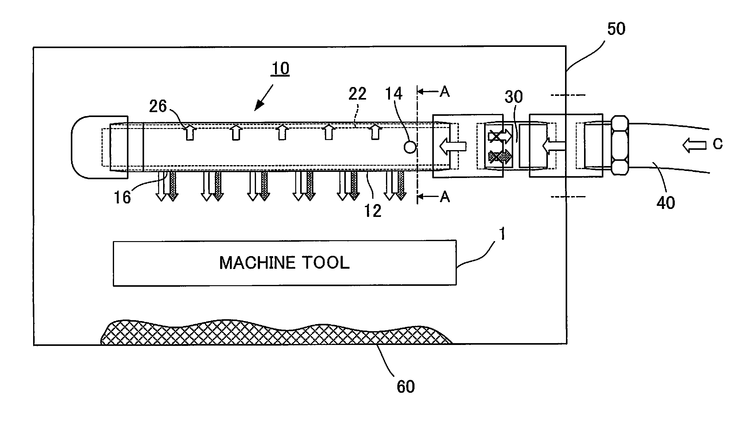
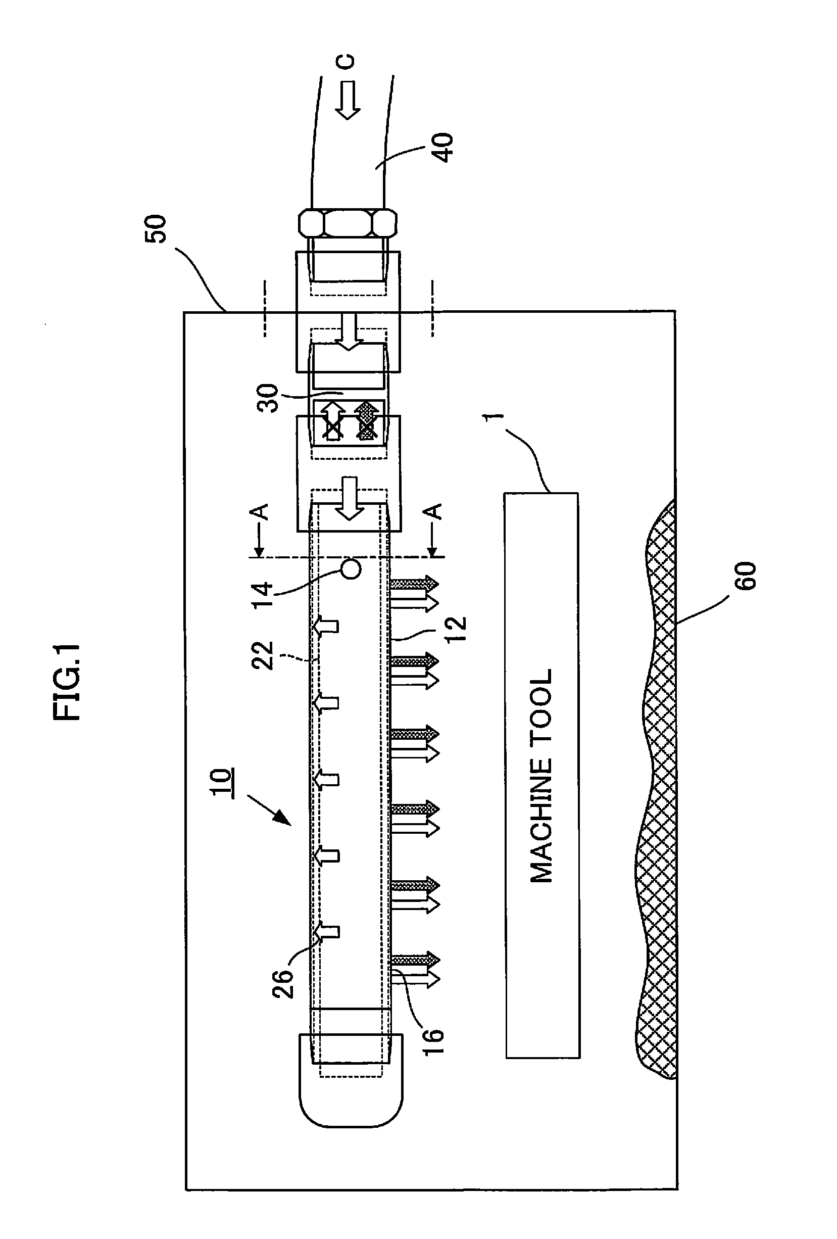
[0025]FIG. 1 is a schematic diagram showing an interior cleaning device for a machine tool according to a present embodiment. An interior cleaning device 10 of the present embodiment is installed inside a cover 50 inside which a machining section 1 of a machine tool is installed, and chips 60 produced by machining by the machine tool are accumulated inside the cover 50. Additionally, it is sufficient if the cover 50 is structured to cover at least the periphery of the machining section of the machine tool.
[0026]The reference numeral 40 refers to a hose, and coolant C is supplied thereto from an outside pump, not shown in the figure. The coolant C which has been supplied is supplied into the interior cleaning device 10 via a check valve 30. The check valve 30 is provided connected to a second pipe 22, described below, on the inside, and is structured such that the coolant C or air described below does not flow backward in the direction of the hose 40.
[0027]The interior cleaning devic...
PUM
 Abstract
Description
Claims
Application Information