Liquid injection needle for jetting a liquid in a predetermined angle range and method of producing the same

A technology of injection needles and angle ranges, which is applied in the field of liquid injection needle components, and can solve difficult problems such as treatment

Inactive Publication Date: 2006-10-04
MATSUMOTO DENTAL UNIVERSITY
View PDF3 Cites 6 Cited by
  • Summary
  • Abstract
  • Description
  • Claims
  • Application Information

AI Technical Summary

Problems solved by technology

In this case, the shape of the cannula changes during the treatment, thus making it difficult to treat precisely and properly

Method used


Image

  • Liquid injection needle for jetting a liquid in a predetermined angle range and method of producing the same
  • Liquid injection needle for jetting a liquid in a predetermined angle range and method of producing the same
  • Liquid injection needle for jetting a liquid in a predetermined angle range and method of producing the same

Examples


Embodiment Construction

[0059] Referring to the accompanying drawings, several preferred embodiments of the present invention will now be described.

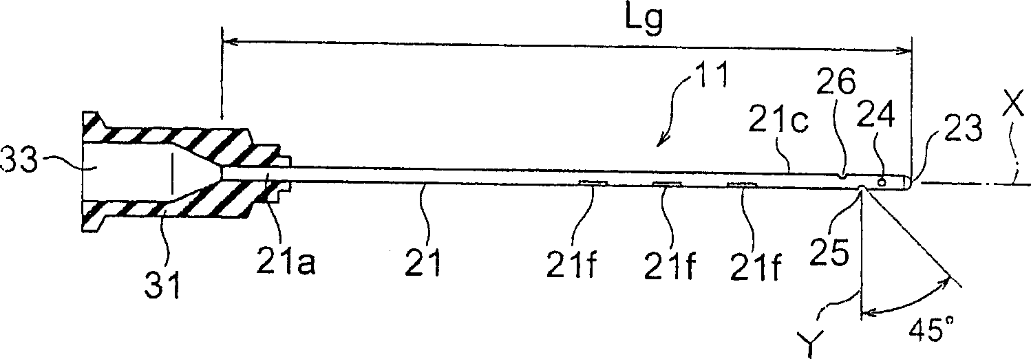
[0060] refer to Figure 1-4 , The liquid injection needle unit 11 according to the first embodiment of the present invention includes a cylindrical cannula 21 and a hub 31 holding the cannula 21 .

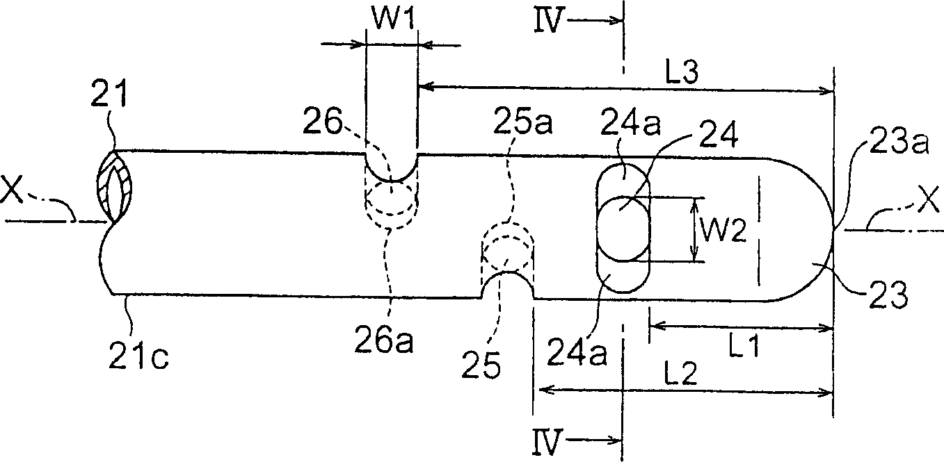
[0061] The cannula 21 is made of a metal material and has a base 21a and a front portion 21c opposed to the base 21a. Base body 21a is supported by needle hub 31 . The front portion 21c has a front end portion 23 as a closed end. The front end portion 23 has a hemispherical outer surface. The front portion 21c of the cannula 21 is provided with a first spout 24, a second spout 25 and a third spout 26 formed on its side wall.

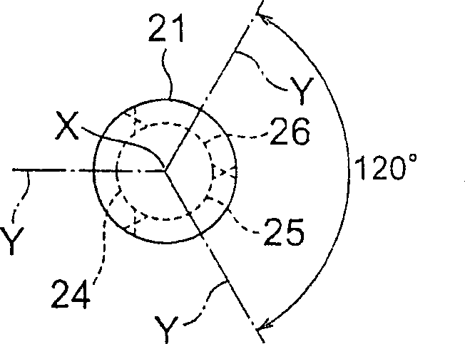
[0062] The first to third nozzles 24 , 25 , 26 are spaced apart from each other along the direction of the central axis X of the cannula 21 . Each of the first to third spouts 24 , 25 , 26 has an orifice axis Y perpendicular to t...


PUM

PropertyMeasurementUnit
diameteraaaaaaaaaa

Abstract

A cannula (21) has a front part (21 c) in a direction of a center axis X with its forward end portion (23) closed. The front part has a plurality of nozzle orifices (24, 25, 26) each of which has an orifice axis Y intersecting the center axis X. Each of the nozzle orifices has a first diameter in a first direction parallel to the center axis X and a second diameter in a second direction perpendicular to the first direction. The first diameter ranges between 0.1 mm and 0.5 mm while the second diameter ranges between 0.1 mm and 0.3 mm so that a liquid in the cannula is jetted from the nozzle orifices in an angle range of 45 degrees towards the forward end portion with respect to the orifice axis.

Description

technical field [0001] The present invention relates to a liquid injection needle element capable of ejecting liquid inside a cannula or needle tube to the outside of the cannula and a method of manufacturing such an element. Background technique [0002] During dental experiments or treatments, it is often necessary to grind teeth. After grinding a tooth, grinding debris left around the tooth sometimes gets into the small gaps at the bottom of the tooth or inside the root canal of the tooth. Those abrasive debris are removed by spraying a liquid (rinse) from the cannula. [0003] In dentistry, cannulas are also used in the treatment of periodontal disease. In this case, the tip portion of the cannula is inserted into the affected part of the periodontal disease, that is, the periodontal pocket (space between the tooth and the gum), and the liquid is sprayed from the cannula. [0004] Japanese Examined Patent Publication (JP-B) No. H06-73530 (Patent Document 1) (correspon...

Claims


Application Information

Patent Timeline
Patent Type & Authority Applications(China)
IPC IPC(8): A61C17/02A61C15/00
CPCA61C5/02A61C5/062B21C37/157A61M5/3291B05C17/00516A61C5/40A61C5/62
Inventor 黑岩昭弘山本昭夫音琴淳一村社孝昭长谷川弘山口岩男
Owner MATSUMOTO DENTAL UNIVERSITY
Why Eureka
Try Eureka