Harvesting apparatus utilizing pressurized fluid

Active Publication Date: 2015-12-24
CRARY INDS
View PDF30 Cites 1 Cited by
  • Summary
  • Abstract
  • Description
  • Claims
  • Application Information

AI Technical Summary

Benefits of technology

The invention is a device called a harvesting apparatus which has a frame for cutting and collecting crop, and a cutting assembly for either severing or accommodating pre-severed crop. The frame has a feed housing for further processing the crop. A fluid delivery system is used to facilitate the cutting and advancement of the crop. The device also has a cleaning assembly for removing debris from the housing. The technical effect of this invention is to provide a more efficient and effective device for harvesting crop.

Problems solved by technology

While these systems have been successful commercially, they have a primary drawback that two separate units for generating pressurized fluid must be purchased, incorporated into the heads, and independently operated.
Optimal performance requires that the units must be synchronized—a state that may be difficult to establish and maintain.
Still further, separate units generally require a large power draw which might compromise a combine's ability to operate efficiently and even simultaneously perform other functions for which it is designed.
Regardless of the capacity of this type of pressurized fluid source, there inevitably results a significant variation in pressure of fluid discharging from the drop tube nozzles along the head width.
This can lead to uneven crop delivery and / or localized accumulation that may interfere with efficient combine operation and in the end result in loss of valuable, usable crop.
However, typically there will still be a localized pressure reduction around the baffle that may compromise overall system performance.
Another problem that has plagued the industry is the unwanted accumulation of crop at the rear of the frame at a feed housing on the frame through which accumulated crop is directed for delivery to a combine for processing thereby.
This accumulation may progressively increase to the point that it interferes with a desired steady volume of flow of crop from the head to the combine.
This results in an interruption of the harvesting operation and also is burdensome to the combine operator.
This crop accumulation could also interfere with the operator's visual monitoring of the head as the combine is advanced.

Method used


Image

  • Harvesting apparatus utilizing pressurized fluid
  • Harvesting apparatus utilizing pressurized fluid
  • Harvesting apparatus utilizing pressurized fluid

Examples


Embodiment Construction

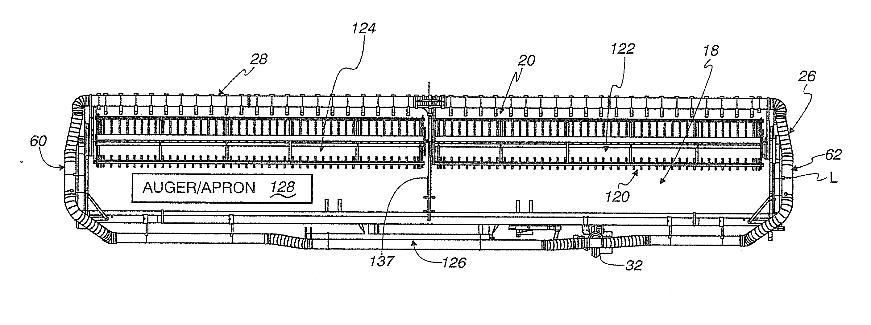
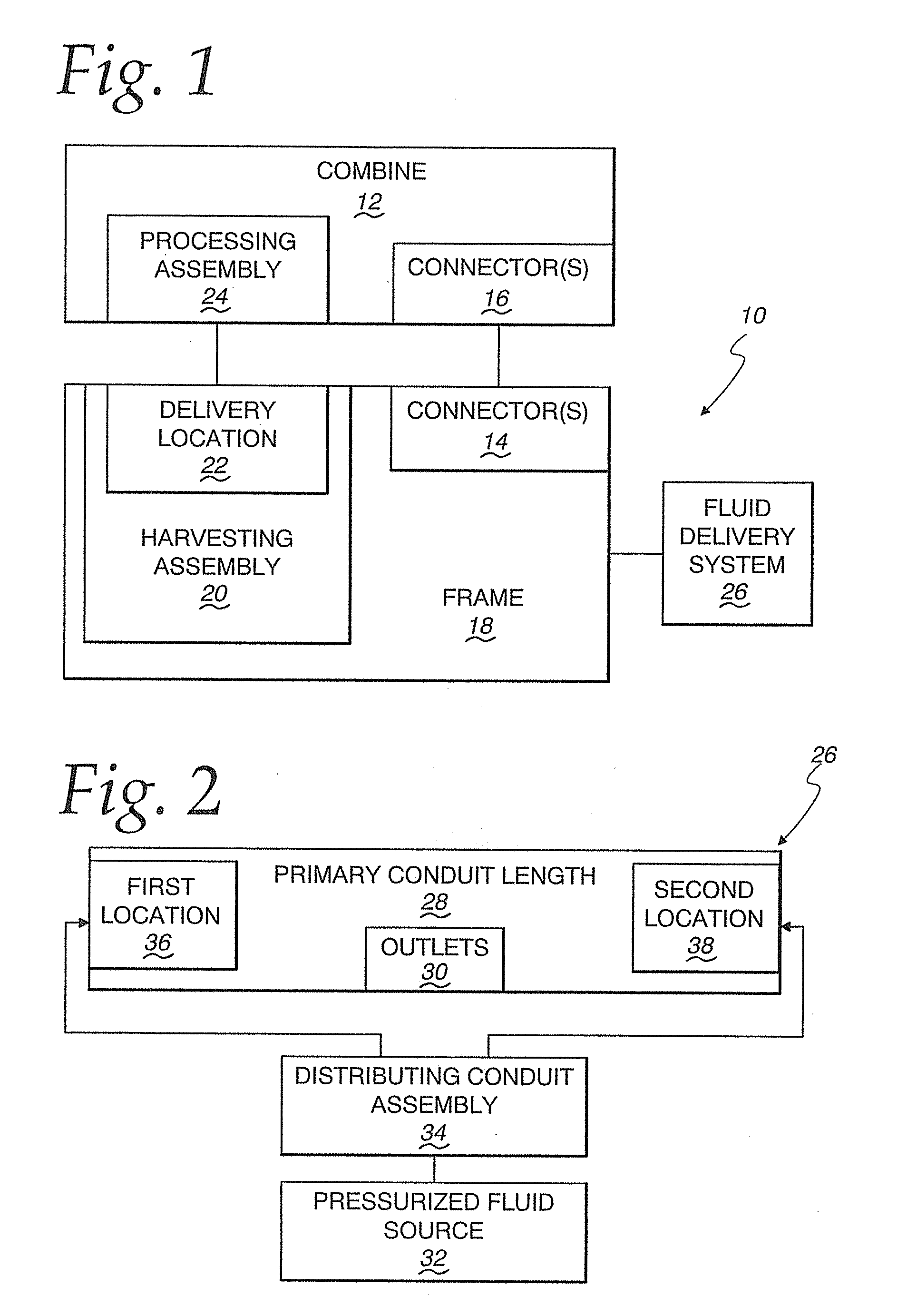
[0056]In FIG. 1, a harvesting apparatus, according to the present invention, is shown schematically at 10. The harvesting apparatus 10, commonly referred to as a “head”, is designed for use in conjunction with a combine 12 through which the harvesting apparatus 10 is advanced over a field in which crop has been grown. Typically, the harvesting apparatus 10 and combine 12 will be releasably joined through cooperating connectors 14, 16, respectively on the harvesting apparatus 10 and combine 12.

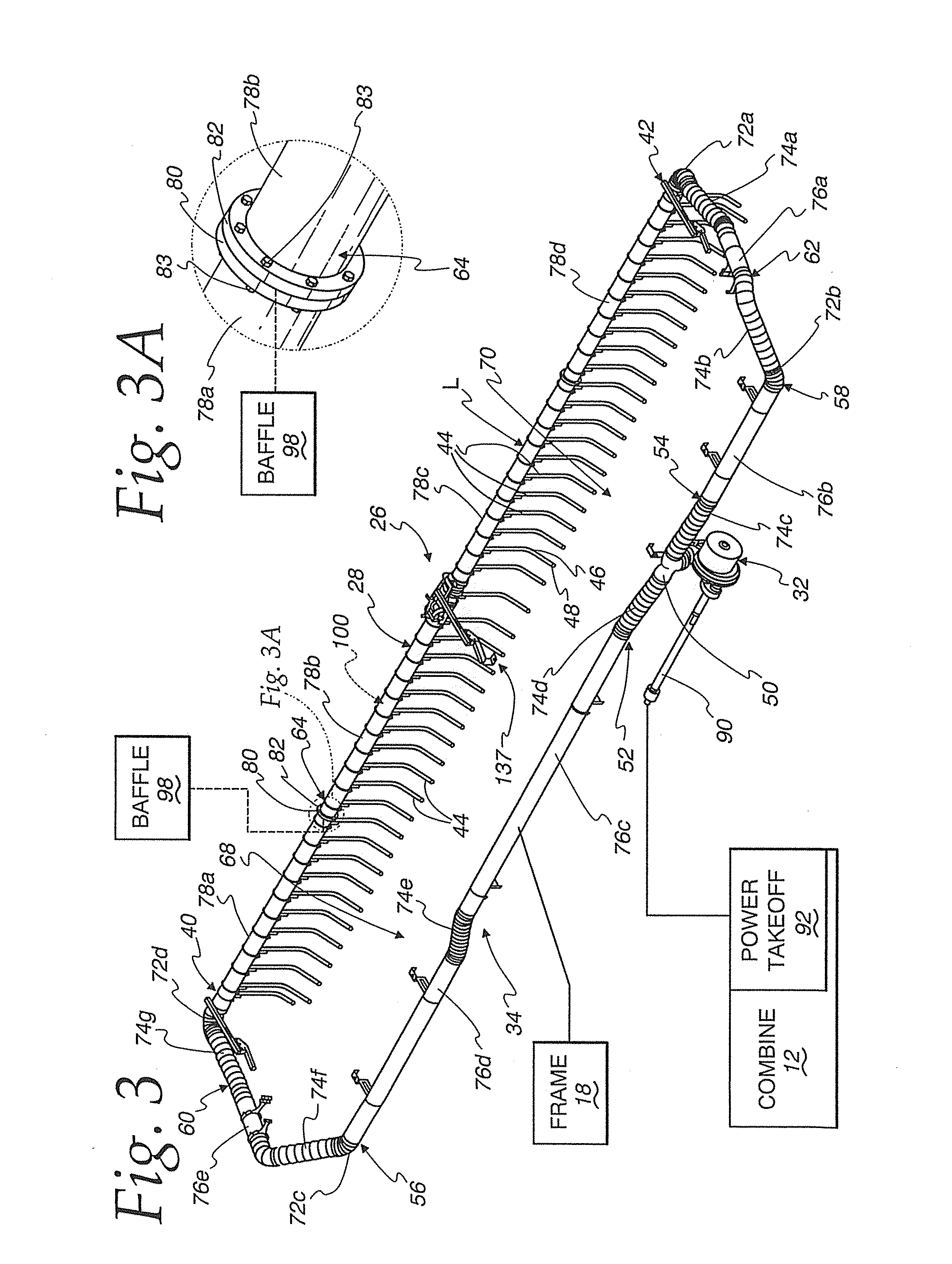
[0057]The harvesting apparatus 10 consists of a frame 18 that is advanced by the combine 12 and supports the operating components for the harvesting apparatus 10. The frame 18 has laterally spaced sides, a front, and a rear.

[0058]The harvesting apparatus 10 may have a different configuration depending upon the particular crop being harvested. As just examples, the crop may be soybeans, a cereal crop, corn, etc.

[0059]A harvesting assembly 20 on the frame 18 is configured to process crop over a w...


PUM


Abstract

A harvesting apparatus having a frame to be advanced over an area in which a crop is grown and a harvesting assembly on the frame configured to process severed crop. The harvesting assembly is configured to advance severed crop laterally to a delivery location between the laterally spaced sides of the frame and to and through a feed housing. A fluid delivery system discharges pressurized fluid to at least one of: a) facilitate severance of crop; and b) facilitate rearward advancement of severed crop. The fluid delivery system has at least a first pressurized fluid source through which pressurized fluid is delivered to laterally spaced outlets. A cleaning assembly has a first cleaning conduit assembly for directing pressurized fluid from the first pressurized fluid supply source in at least a first stream that repositions unusable crop and debris to reduce buildup thereof in the vicinity of the feed housing.

Description

BACKGROUND OF THE INVENTION[0001]1. Field of the Invention[0002]This invention relates to a harvesting apparatus and, more particularly, to a harvesting apparatus that utilizes pressurized fluid to assist the movement of crop that is cut by the apparatus and / or in a pre-cut state in a field preparatory to processing by the apparatus.[0003]2. Background Art[0004]A basic harvesting system utilizes a combine that separates usable crop from stalks, vines, etc. A wide range of different crops are accumulated and delivered to the combine through a harvesting head. The harvesting heads take different forms based upon the particular crop that is being harvested. Even for the same crop, myriad different designs exist with different operational capabilities.[0005]The heads have different constructions depending upon whether they are designed to sever the crop or handle pre-cut crop. In the former case, cutting may be effected by stationary cutting edges or by edges formed on components that m...

Claims


Application Information

Patent Timeline
IPC IPC(8): A01D57/01A01D61/00
CPCA01D61/00A01D57/01A01D61/008
Inventor CAVKUSIC, DAMIRRICHARD, BENLEE, MITCHELLROSS, DANIEL
Owner CRARY INDS
Why Eureka
Try Eureka