Imaging device and imaging method

a technology of imaging device and image data, which is applied in the direction of semiconductor devices, color television details, television systems, etc., can solve the problems of inability to communicate between the interchangeable lens and inability to acquire information from the camera main body, and inability to detect ghost images included in the image data at the smaller diaphragm diameter

Active Publication Date: 2016-06-23
FUJIFILM CORP
View PDF2 Cites 9 Cited by
  • Summary
  • Abstract
  • Description
  • Claims
  • Application Information

AI Technical Summary

Benefits of technology

[0037]According to the present invention, the optical diaphragm and the electronic diaphragm are used in combination. Accordingly, ghost light can be eliminated by both the optical diaphragm and the electronic diaphragm. Further, it is possible to detect the current aperture value

Problems solved by technology

Further, ghost images included in the image data at the smaller diaphragm diameter cannot be detected.
However, in this case, there are problems in that communication between the i

Method used


Image

  • Imaging device and imaging method
  • Imaging device and imaging method
  • Imaging device and imaging method

Examples


Embodiment Construction

[0052]Hereinafter, referring to accompanying drawings, preferred embodiments of an imaging device and an imaging method according to the present invention will be described.

[0053]

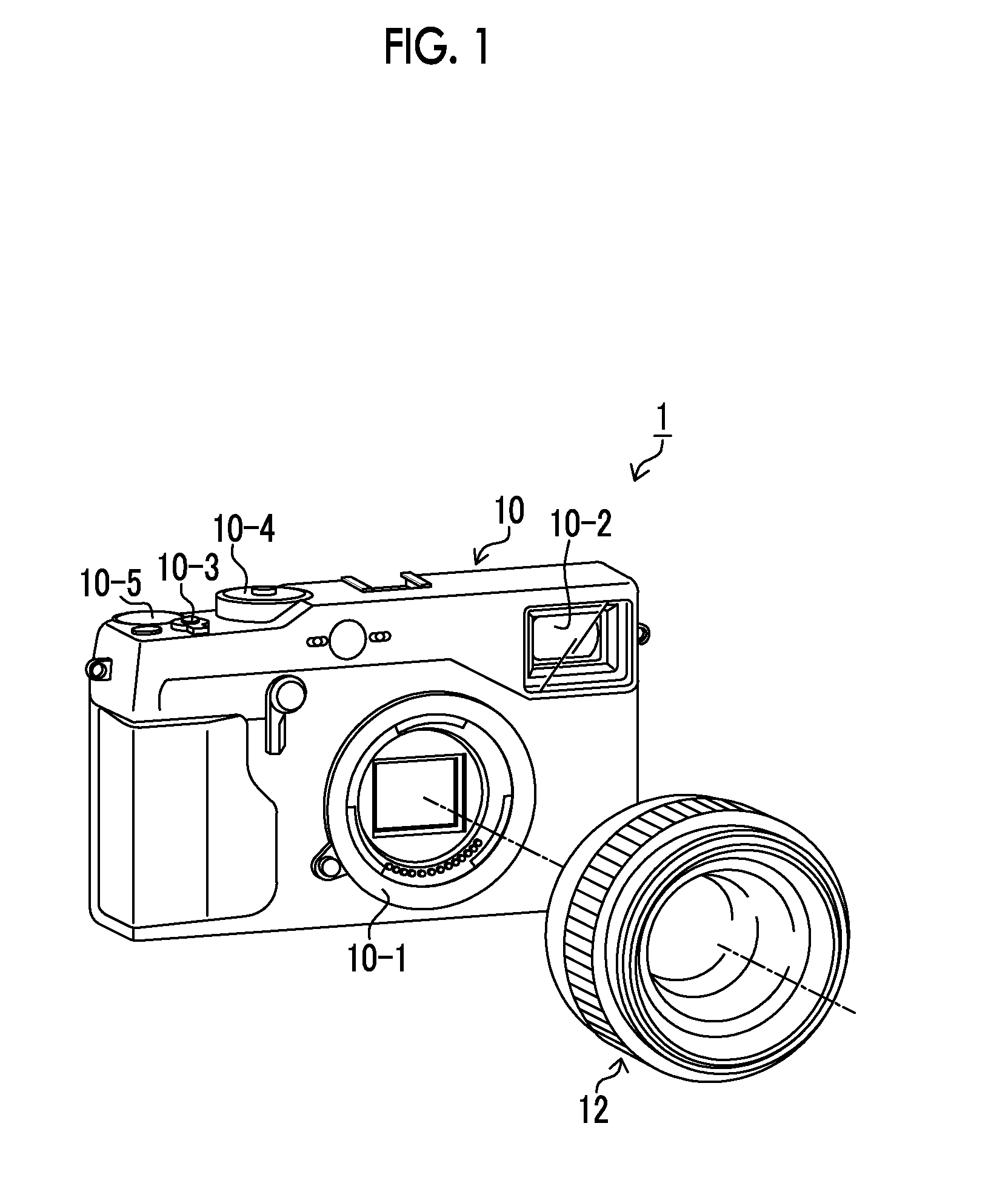
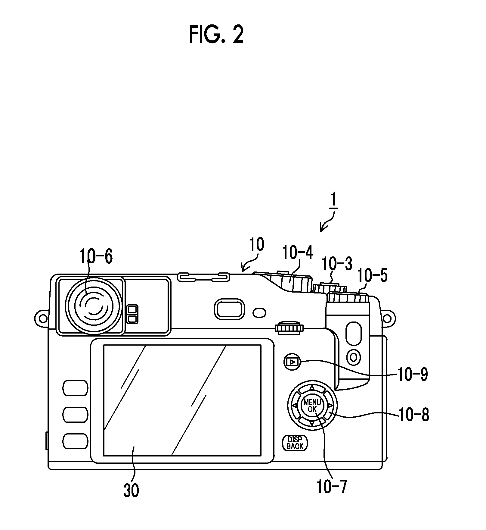
[0054]FIG. 1 is a perspective view of an imaging device according to the present invention as viewed from the front thereof. FIG. 2 is a rear view of the imaging device.

[0055]As shown in FIG. 1, the imaging device 1 includes a camera main body 10, and an interchangeable lens (optical imaging system) 12 which is detachably mounted on the camera main body 10.

[0056]A mount 10-1 on which the interchangeable lens unit 12 is mounted, a finder window 10-2 of an optical finder, and the like are provided on the front of the camera main body 10. A shutter release button 10-3, a shutter speed dial 10-4, an exposure correction dial 10-5, and the like are provided on the upper surface of the camera main body 10.

[0057]Further, as shown in FIG. 2, mainly a liquid crystal monitor 30, an eyepiece section 10-6 of the optical...


PUM


Abstract

The imaging device of the present invention includes: an image sensor 14 that is configured such that a plurality of pixels having an organic layer (14-4) for photoelectric conversion is two-dimensionally arranged, and each pixel of the image sensor (14) is divided into a plurality of regions, and has an on-chip microlens (15), which forms a pupil image of a optical imaging system on the plurality of regions, and reading sections (16) which respectively read photoelectrically converted signals of the plurality of divided regions; an optical diaphragm that mechanically stops down rays which are incident into the image sensor 14; and an electronic diaphragm section that electronically controls an aperture value, and that selects signals of the divided regions corresponding to the aperture value from the signals of the plurality of divided regions, on the basis of the aperture value which is controlled by the optical diaphragm.

Description

CROSS-REFERENCE TO RELATED APPLICATIONS[0001]This application is a Continuation of PCT International Application No. PCT / JP2014 / 073639 filed on Sep. 8, 2014, which claims priority under 35 U.S.C. §119(a) to Japanese Patent Application No. 2013-202084 filed on Sep. 27, 2013. Each of the above applications is hereby expressly incorporated by reference, in their entirety, into the present application.BACKGROUND OF THE INVENTION[0002]1. Field of the Invention[0003]The present invention relates to an imaging device and an imaging method. In particular, the present invention relates to an imaging device, which has an image sensor in which an organic layer serves as a photoelectric conversion section, and an imaging method therefor.[0004]2. Description of the Related Art[0005]In the past, there has been proposed an imaging device including: an imaging lens that has an aperture diaphragm; an imaging element that keeps a traveling direction of rays invariant, receives the rays, and generates...

Claims


Application Information

Patent Timeline
IPC IPC(8): H04N5/235H01L27/30H04N5/359
CPCH04N5/2352H01L27/307H04N5/2351H04N5/3597H01L27/14605H01L27/14625H01L27/14627H01L27/14667H04N23/75H04N23/76H04N23/71H04N25/61H04N25/134H04N23/72H04N25/626H10K39/32
Inventor AOKI, TAKASHIOOTSUKI, YASUO
Owner FUJIFILM CORP
Why Eureka
Try Eureka