Power converter and device integrating inductors in parallel of the same

Active Publication Date: 2016-10-13
DELTA ELECTRONICS INC
View PDF23 Cites 9 Cited by
  • Summary
  • Abstract
  • Description
  • Claims
  • Application Information

AI Technical Summary

Benefits of technology

[0006]The disclosure provides a device integrating a plurality of inductors in parallel. The device includes a plurality of windings and a magnetic core structure. A number of the windings corresponds to a number of the inductors. The magnetic core structure includes a plurality o

Problems solved by technology

In a power converter, magnetic components occupy a certain degree of the volume and contribute a certain degree

Method used


Image

  • Power converter and device integrating inductors in parallel of the same
  • Power converter and device integrating inductors in parallel of the same
  • Power converter and device integrating inductors in parallel of the same

Examples


Embodiment Construction

[0025]Reference will now be made in detail to the present embodiments of the disclosure, examples of which are illustrated in the accompanying drawings. Wherever possible, the same reference numbers are used in the drawings and the description to refer to the same or like parts.

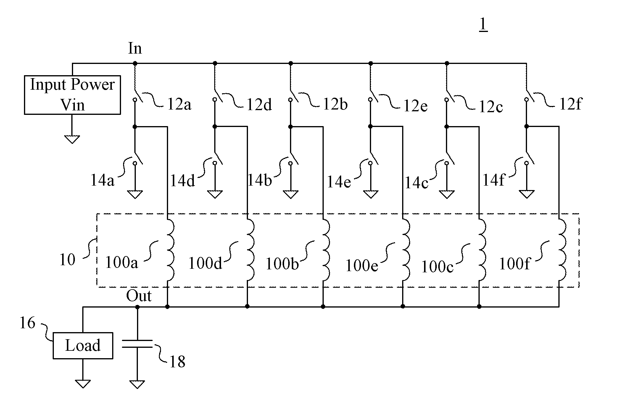
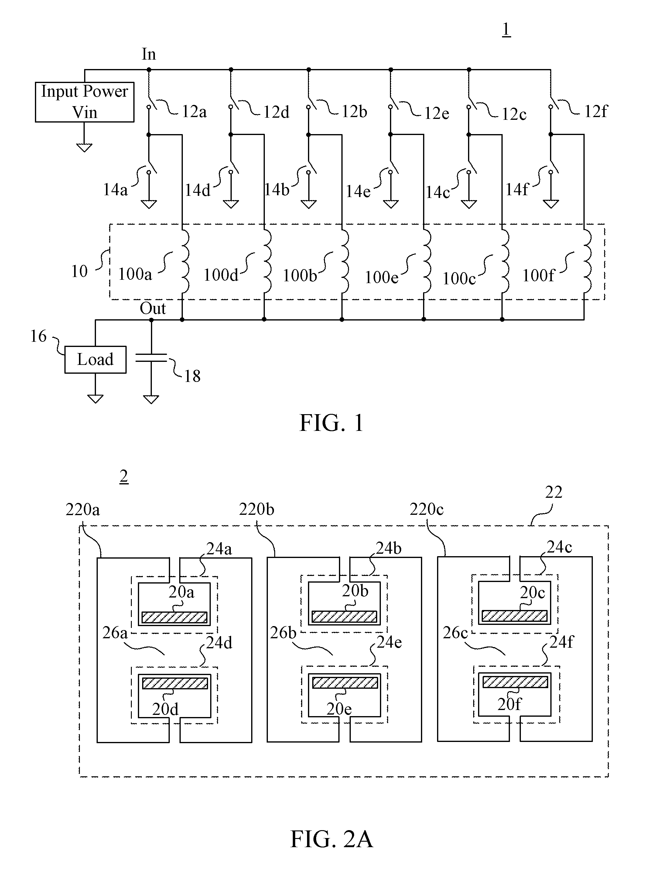
[0026]Reference is now made to FIG. 1. FIG. 1 is a circuit diagram of a power converter 1 in an embodiment of the present disclosure. The power converter 1 includes an inductor module 10, a plurality of switching devices 12a-12f, 14a-14f and a load 16.

[0027]The inductor module 10 is electrically connected to a parallel-connected output terminal OUT of the power converter 1. As a result, the inductor module 10 is the output inductor of the power converter 1 corresponding to the parallel-connected output terminal OUT. The inductor module 10 includes a plurality of inductors 100a-100f.

[0028]The switching devices 12a-12f and the corresponding switching devices 14a-14f form a plurality of power conversion circuit...


PUM


Abstract

A device is provided that integrates a plurality of inductors in parallel. The device includes a plurality of windings and a magnetic core structure. A number of the windings corresponds to a number of the inductors. The magnetic core structure includes a plurality of windows, wherein each window includes at least two windings coupled with each other. When a phase difference of the voltage phases is smaller than a predetermined value, voltage phases of two terminals of any two of the windings within the same window are substantially the same.

Description

RELATED APPLICATIONS[0001]This application claims priority to China Application Serial Number 201510168948.2, filed Apr. 10, 2015, which is herein incorporated by reference.FIELD OF INVENTION[0002]The present disclosure relates to a power technology. More particularly, the present disclosure relates to a power converter and an integrated device of the same.DESCRIPTION OF RELATED ART[0003]In recent years, miniaturization of power converter is an important trend of the development of power technology. In a power converter, magnetic components occupy a certain degree of the volume and contribute a certain degree of the loss. Therefore, the design and improvement of the magnetic components becomes very important.[0004]In some application scenarios, such as an application with large current condition, a plurality of paths of circuits connected in parallel are used to decrease the occurrence of the ripples. In common designs of the magnetic components, in order to guarantee the unsaturati...

Claims


Application Information

Patent Timeline
IPC IPC(8): H01F27/24H02M3/04H01F27/28
CPCH01F27/24H02M3/04H01F27/2804H01F27/2823H02M3/1584H01F3/14H01F37/00H02M1/0064H02M3/1586
Inventor WU, RUIZENG, JIAN-HONGZHOU, MINXIE, YI-CONG
Owner DELTA ELECTRONICS INC
Why Eureka
Try Eureka