Imaging method of a zone of a patient's body superposing distance marking

US20160317105A1Inactive Publication Date: 2016-11-03GENERAL ELECTRIC CO
0 Cites 1 Cited by

Patent Information

Authority / Receiving Office
US · United States
Current Assignee / Owner
Publication Date
2016-11-03
Estimated Expiration
Not applicable · inactive patent

Smart Images

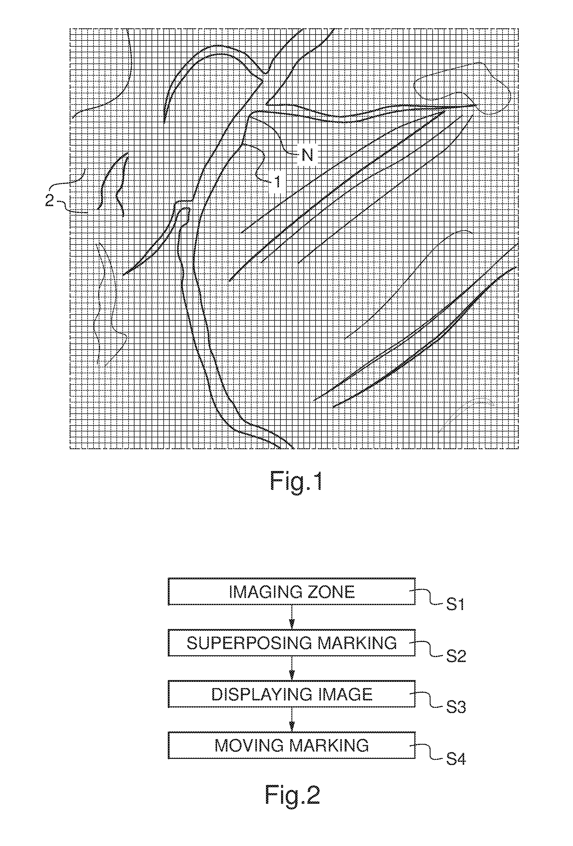
  • Figure 1
    Figure 1
  • Figure 2
    Figure 2
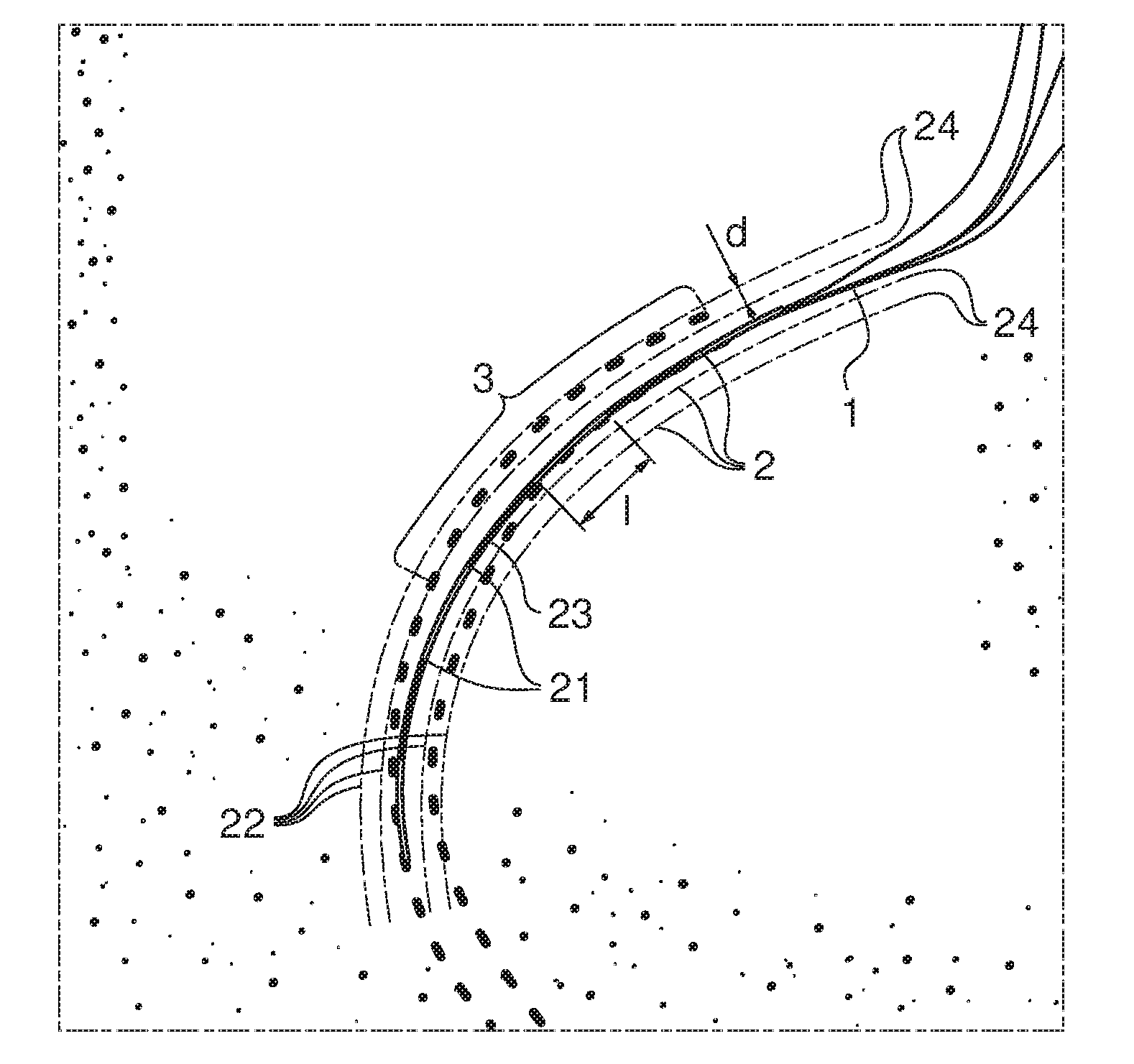
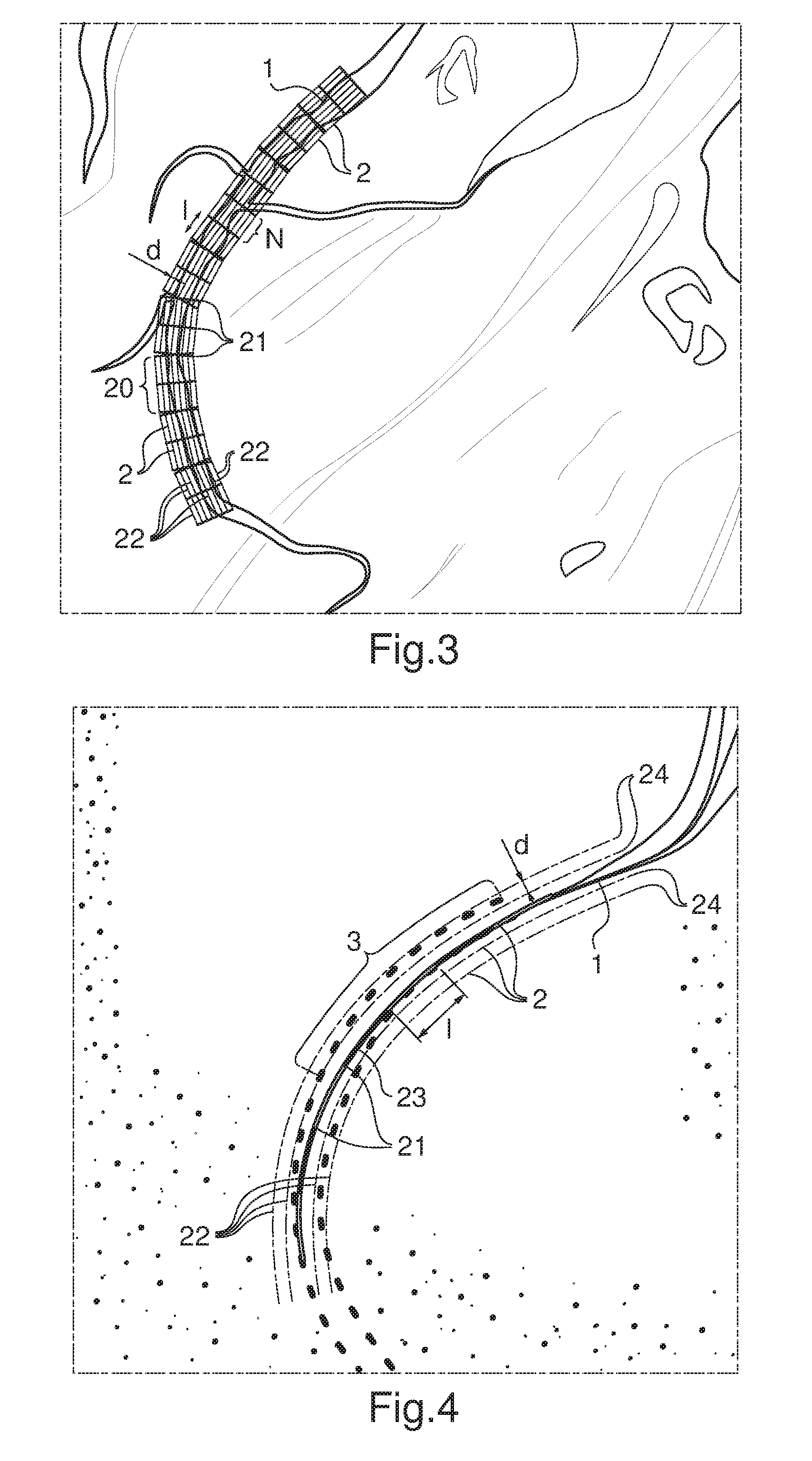
  • Figure 3
    Figure 3
Patent Text Reader

Abstract

This invention relates to an imaging method of a zone of a patient's body, comprising: imaging said zone including an object of interest, superposing at least one graphical marking with regular and known spacing to said object of interest to make a combined image of said zone, displaying said combined image, wherein said marking orientation is similar to the orientation of said object of interest on said combined image.
Need to check novelty before this filing date? Find Prior Art

Description

FIELD OF THE INVENTION

[0001] The invention relates to imaging methods of a zone of a patient's body superposing distance marking and to combined images superposing distance marking to a zone of a patient's body on the same image.BACKGROUND OF THE INVENTION

[0002] The radiologist or the clinician, when imaging a part of a patient's body, and when looking at displayed image to discover whether there is a problem in this part of a patient's body, need to be able to easily and intuitively evaluate distances and surfaces in medical images.

[0003] According to a prior art shown on FIG. 1, it is known to display over the image a set of landmarks with uniform regular known spacing. This set of landmarks is always a uniform regular generic grid covering the full extent of the image, independently of the image content.

[0004] However, according to invention finding, this type of rectangular bi-dimensional grid is of little utility when the orientation of the objects to be measured is not at all alig...

Examples

Embodiment Construction

[0039]FIG. 1 shows an example of a vascular image including a marking according to prior art. On the vascular image, there is a vessel 1 to which is superposed a rectangular bi-dimensional uniform grid 2. This vessel 1 which is the object of interest presents a narrowing N which is a region of interest. Unfortunately, in present case, the orientation of the vessel 1 at the level of the narrowing N is not parallel to any of the axis of the grid 2. Therefore, it is not easy, for the clinician, to be able to perform any visual distance measurement, with respect to narrowing N, either concerning the length of the narrowing N along the vessel 1 or concerning the diameter of the narrowing N across the vessel 1, with the help of the uniform bi-dimensional grid 2.

[0040]FIG. 2 shows an example of steps performed by an imaging method according to embodiments of the invention. The imaging method comprises successively a step S1 of imaging zone, a step S2 of superposing marking, a step S3 of di...