Elevator

a technology of elevators and lifts, applied in the field of elevators, can solve the problems of insufficient reliability or inability to prevent the further insufficient reliability of mechanical shape locking between the drive wheel and the rope engaging the drive wheel, etc., to facilitate the safety and reliability of the system, prevent the development of the problem into even more hazardous state, and quickly and effectively react to the effect of problems

Active Publication Date: 2016-11-24
KONE CORP
View PDF2 Cites 5 Cited by
  • Summary
  • Abstract
  • Description
  • Claims
  • Application Information

AI Technical Summary

Benefits of technology

[0007]It is brought forward a new elevator comprising a first elevator unit vertically movable in a hoistway, and a second elevator unit vertically movable in a hoistway, at least one of said elevator units being an elevator car for receiving a load to be transported i.e. goods and / or passengers; one or more belt-shaped hoisting ropes interconnecting the first elevator unit and the second elevator unit and rope wheels including a drive wheel for moving said one or more belt-shaped hoisting ropes. Each of said one or more belt-shaped hoisting ropes passes around the drive wheel and comprises consecutively a first rope section extending between the drive wheel and the first elevator unit, and a second rope section extending between the drive wheel and the second elevator unit. The rope wheels further include one or more non-driven, i.e. freely rotating, cambered diverting wheels in proximity of the drive wheel, and each said first rope section is arranged to pass around a non-driven first cambered diverting wheel, in particular resting against a cambered circumferential surface area thereof. The elevator further comprises a rope monitoring arrangement configured to monitor displacement of each of said first rope sections in the axial direction of the rope wheels away from a predefined zone, and displacement of each of the second rope sections in the axial direction of the wheels away from a predefined zone. The elevator is configured to stop the rotation of the drive wheel when one or more of the first and second rope sections is displaced in the axial direction of the rope wheels away from a predefined zone, such as over a limit position delimiting the predefined zone. With this configuration, running of a rope outside its intended course in axial direction of the rope wheels, and further development of the problem into even more hazardous are prevented. Due to the monitoring arrangement, abnormal situations with regard to position of either rope section of a rope are detected and reacted to quickly and effectively, whereby safety and reliability of the system are facilitated, which is important because the axial control of rope position is provided largely by cambered rope wheel shape. By monitoring displacement of both the first and second rope section, it is also possible enabled that the elevator can be further controlled on the basis of displacement information, such as which of the rope sections is displaced or was displaced first,

Problems solved by technology

A drawback of the known elevators has been that moving of a rope in the axial direction outside its intended course, and further development of the problem into even more hazardous state have not been prevented in an adequately reliable manner.
This has been difficult especially with elevators where said mechanical shape-locking between the drive wheel and the rope engaging the drive wheel has been inadequately reliable or unavailable for some reason such as due to preference to utilize cambered shape of the drive wheel for rope position control.

Method used


Image

  • Elevator
  • Elevator
  • Elevator

Examples


first embodiment

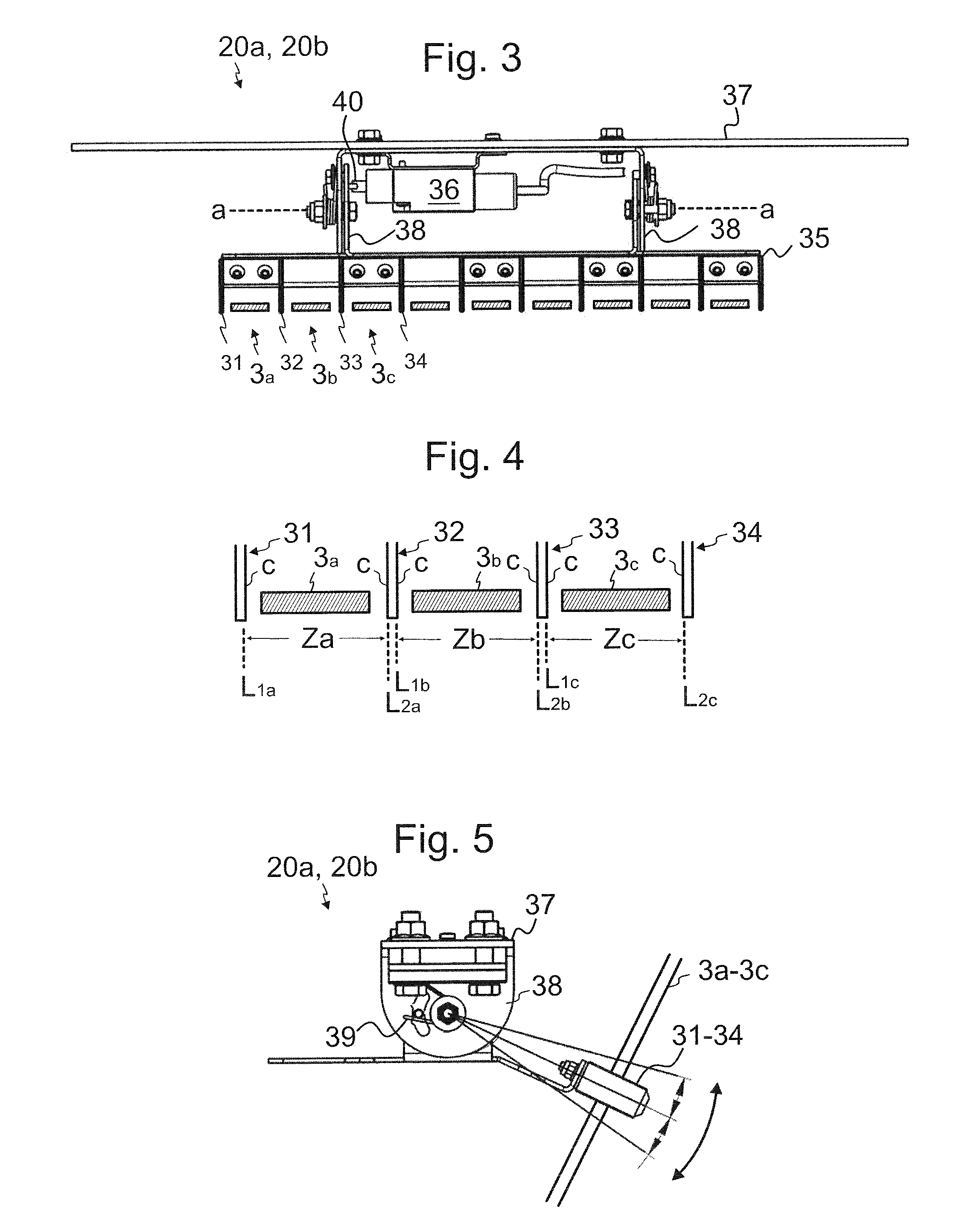
[0097]FIG. 3 illustrates a preferred first embodiment for the detector 20a,20b. The detector 20a,20b comprises for each rope on opposite sides of the rope 3a,3b,3c in said axial direction of the wheels 4,5,6 a first and a second sensing member 31,32; 32, 33; 33,34. In the embodiment as illustrated, there are several ropes whereby there are sensing members which extend between the ropes next to each other. Each sensing member comprises a contact face c which the rope next to it can contact when the rope in question is displaced in said axial direction. Each first sensing member 31,32,33 is positioned at the first limit position L1a,L1b,L1c of the rope in question, such that a contact face c thereof is positioned at the point of the limit position L1a,L1b,L1c. Each second sensing member 32,33,34 is positioned correspondingly at the second limit position L2a,L2b,L2c of the rope in question such that a contact face c thereof is positioned at the point of the limit position L2a,L2b,L2c, ...

second embodiment

[0102]FIG. 6 illustrates a second embodiment for the detector 30a,30b. The detector 30a,30b comprises sensing devices 52-55 for receiving electromagnetic radiation or ultrasonic sound from said limit positions L1a,L2a,L1b,L2b;L1c,L2c and a monitoring unit 51, connected to the sensing devices and arranged to trigger said stopping of the drive wheel 5 if electromagnetic radiation or ultrasonic sound received from one or more of said limit positions L1a,L2a;L1b,L2b,L1c,L2c meet(s) predetermined criteria, such as reaches a predetermined limit or changes in a predetermined way. Each sensing device 52-55 may be in the form of a photocell, infrared, microwave or laser beam sensor, ultrasonic sound sensor for instance. Said sensing devices 52-55 each comprise a receiver for receiving electromagnetic radiation or ultrasonic sound from a limit position L1a,L2a;L1b,L2b,L1c,L2c it is associated with. FIG. 7 illustrates a preferred structure for a sensing device of 52,53,54,55. Preferably, in ad...


PUM


Abstract

An elevator includes a first elevator unit vertically movable in a hoistway, and a second elevator unit vertically movable in a hoistway. At least one of said elevator units is an elevator car. One or more belt-shaped hoisting ropes interconnects the first elevator unit and the second elevator unit. A drive wheel is provided for moving said one or more belt-shaped hoisting ropes. Each of the belt-shaped hoisting ropes passes around the drive wheel and includes consecutively a first rope section extending between the drive wheel and the first elevator unit, and a second rope section extending between the drive wheel and the second elevator unit. The elevator further includes non-driven cambered diverting wheels, each said first rope section being arranged to pass around a first cambered diverting wheel, in particular resting against a cambered circumferential surface area thereof, and each the second rope section being arranged to pass around a second cambered diverting wheel, in particular resting against a cambered circumferential surface area thereof. A rope monitoring arrangement is configured to monitor displacement of each of the first rope sections in the axial direction of the wheels away from a predefined zone, and displacement of each of the second rope sections in the axial direction of the wheels away from a predefined zone. The elevator is configured to stop the rotation of the drive wheel when one or more of the first and second rope sections is displaced in the axial direction of the wheels away from a predefined zone.

Description

FIELD OF THE INVENTION[0001]The invention relates to an elevator for transporting passengers and / or goods.BACKGROUND OF THE INVENTION[0002]An elevator typically comprises an elevator car and a counterweight, which are vertically movable in a hoistway. These elevator units are interconnected to each other by a hoisting roping. The hoisting roping is normally arranged to suspend the elevator units on opposite sides of a drive wheel. For providing force for moving the suspension roping, and thereby also for the elevator units, the elevator comprises a motor for rotating the drive wheel engaging the hoisting roping. The motor is automatically controlled by an elevator control system, whereby the elevator is suitable for automatically serving passengers.[0003]In elevators, the hoisting roping comprises at least one but typically several elevator ropes passing alongside each other. The conventional elevators have steel ropes, but some elevators have ropes that are belt-shaped, i.e. their ...

Claims


Application Information

Patent Timeline
Patent Type & Authority Applications(United States)
IPC IPC(8): B66B5/02B66B5/00B66B1/30B66B9/00B66B7/12
CPCB66B5/027B66B9/00B66B5/0031B66B1/30B66B7/1215B66B5/0018B66B7/10B66B11/0035B66B11/04B66B5/00B66B5/0006B66B7/06
Inventor HELENIUS, JUHA
Owner KONE CORP
Why Eureka
Try Eureka