[0006]The object of the invention is to provide an improved elevator as well as a method. The object of the invention is, inter alia, to alleviate previously described drawbacks of known solutions and problems discussed or implied later in the description of the invention. The object of the invention is to introduce an elevator and a method where rope position on the drive wheel can be simply, reliably and safely controlled. In particular, an elevator is introduced where running of a rope outside its intended course, and further development of the problem into even more hazardous state are prevented. Embodiments are presented, inter alia, in which after reacting to a problem situation with regard to rope position, the elevator can be brought to a safer state, and even recovered such that the passengers can be let out of the car. Embodiments are presented, inter alia, in which said objects are realized with simple and reliable configuration.
[0007]It is brought forward a new elevator comprising a first elevator unit vertically movable in a hoistway, and a second elevator unit vertically movable in a hoistway, at least one of said elevator units being an elevator car for receiving a load to be transported i.e. goods and / or passengers; one or more belt-shaped hoisting ropes interconnecting the first elevator unit and the second elevator unit and rope wheels including a drive wheel for moving said one or more belt-shaped hoisting ropes. Each of said one or more belt-shaped hoisting ropes passes around the drive wheel and comprises consecutively a first rope section extending between the drive wheel and the first elevator unit, and a second rope section extending between the drive wheel and the second elevator unit. The rope wheels further include one or more non-driven, i.e. freely rotating, cambered diverting wheels in proximity of the drive wheel, and each said first rope section is arranged to pass around a non-driven first cambered diverting wheel, in particular resting against a cambered circumferential surface area thereof. The elevator further comprises a rope monitoring arrangement configured to monitor displacement of each of said first rope sections in the axial direction of the rope wheels away from a predefined zone, and displacement of each of the second rope sections in the axial direction of the wheels away from a predefined zone. The elevator is configured to stop the rotation of the drive wheel when one or more of the first and second rope sections is displaced in the axial direction of the rope wheels away from a predefined zone, such as over a limit position delimiting the predefined zone. With this configuration, running of a rope outside its intended course in axial direction of the rope wheels, and further development of the problem into even more hazardous are prevented. Due to the monitoring arrangement, abnormal situations with regard to position of either rope section of a rope are detected and reacted to quickly and effectively, whereby safety and reliability of the system are facilitated, which is important because the axial control of rope position is provided largely by cambered rope wheel shape. By monitoring displacement of both the first and second rope section, it is also possible enabled that the elevator can be further controlled on the basis of displacement information, such as which of the rope sections is displaced or was displaced first,
[0008]In a preferred embodiment, each said second rope section is arranged to pass around a second non-driven cambered diverting wheel, in particular resting against a cambered circumferential surface area thereof. Advantageously, the configuration thus provides, independently of drive direction, pre-guidance with a cambered wheel shape for the rope sections arriving at the drive wheel, as well as post-guidance with cambered wheel shape for the rope sections departing from the drive wheel. Thus, axial position can be ensured with both directions of movement of the rope(s). This is because axial rope position is predominantly controlled by the cambered diverting wheel which the rope enters first, which has now been found out by experimental work and analyses. Due to the monitoring arrangement, abnormal situations with regard to position of either rope section of a rope are reacted to quickly and effectively, whereby safety and reliability of the system are facilitated, which is important because the axial control of rope position is provided largely by cambered shape of the diverting wheels.
[0012]In a preferred embodiment, when the drive wheel is rotated slowly backwards such that the car moves substantially slower than the nominal speed of the elevator. Thus, rope velocity, as well as car velocity can be maintained relatively safe and low so that risk of injuries is reduced in case a sudden stop still needs to be performed. Further, it is preferable that when the drive wheel is rotated slowly backwards, the circumferential speed of the drive wheel is preferably maintained constant.
[0013]In a preferred embodiment, when the drive wheel is rotated slowly backwards, the circumferential speed of the drive wheel is limited to be less than 2 m / s, preferably less 1 m / s. Thus, rope velocity, as well as car velocity can be maintained relatively safe and low so that risk of injuries is reduced in case a sudden stop needs to be performed. Further, it is preferable that when the drive wheel is rotated slowly backwards, the circumferential speed of the drive wheel is maintained constant. The elevator is preferably such that the circumferential speed of the drive wheel is substantially higher than said (limit) speed, when the car is moved with nominal speed of the elevator.
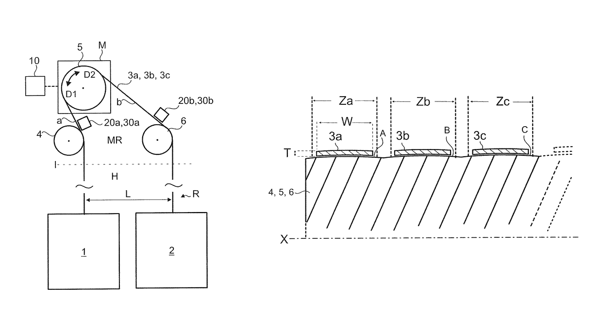
[0045]In a preferred embodiment, both the first and second rope section diverge from the drive wheel towards the same lateral side thereof, the first rope section a passing over a first cambered diverting wheel, in particular resting against a cambered circumferential surface area thereof, and therefrom straight down to the first elevator unit, and the second rope section b passing over a second cambered diverting wheel, in particular resting against cambered circumferential surface area thereof, and therefrom straight down to the second elevator unit. It has been found by experimental work and analyzing that certain minimum contact length between rope and a cambered diverting wheel is required to ensure proper control of rope position in axial direction of the cambered diverting wheel. When the drive wheel has been positioned such relative to diverting wheels that the rope sections of a rope diverge in the defined way from the drive wheel towards the same lateral side thereof, the contact length between rope and the diverter wheel can be without problems be set, with any rope-to-rope distance, to be adequately long to enable the cambered shape to act effectively on the rope. This is realized also when rope-to-rope distance is wider than but close to the diameter of the drive wheel. Thus, with the defined elevator construction also this kind of configuration can be safely implemented.

