Substrate cleaning method, substrate cleaning apparatus, and computer-readable storage medium

a cleaning method and substrate technology, applied in the direction of photomechanical equipment, cleaning using liquids, instruments, etc., can solve the problems of more defective development, defective development, and sometimes defective development, and achieve the effect of preventing the occurrence of defective developmen

Active Publication Date: 2017-02-14
TOKYO ELECTRON LTD
View PDF4 Cites 2 Cited by
  • Summary
  • Abstract
  • Description
  • Claims
  • Application Information

AI Technical Summary

Benefits of technology

[0006]However, the defective development sometimes occurs even by the method of JP2006-080315A. The object of the present invention is to provide a substrate cleaning method, a substrate cleaning apparatus, and a computer-readable storage medium, which are capable of further restraining occurrence of the defective development.
[0009]The larger the size of the intermediate area is, the more the defective development is likely to occur. This is because, when the intermediate area is large, a larger amount of the cleaning liquid is subjected to the centrifugal force by the rotation of the substrate, whereby the larger amount of the cleaning liquid breaks apart and scatters on the surface of the substrate. However, in the substrate cleaning method according to the one aspect of the present invention, when the width of the intermediate area, which is positioned between the wet area, which spreads outward from the supply position of the cleaning liquid on the surface of the substrate, and the dry area, exceeds the predetermined threshold value, the process parameter is changed such that the width of the intermediate area becomes the threshold value or less. Thus, since the width of the intermediate area is prevented from exceeding the predetermined value, the occurrence of liquid scattering which invites the defective development can be significantly restrained. As a result, occurrence of the defective development can be further restrained.
[0010]It may be provided that, in the fifth step, the process parameter to be changed includes at least one of a flow rate of the dry gas ejected from the gas nozzle, a moving speed of the liquid nozzle, a rotating speed of the substrate, and a distance between the gas nozzle and the surface of the substrate. It may be provided that, in the third step, the dry gas is ejected from the gas nozzle to the surface of the substrate, while the gas nozzle is moved from the central side of the substrate to the peripheral side thereof, with the gas nozzle being maintained to be positioned nearer to the central side of the substrate than the liquid nozzle, and in the fifth step, the process parameter to be changed includes at least one of a flow rate of the dry gas ejected from the gas nozzle, a moving speed of the liquid nozzle, a rotating speed of the substrate, and a distance between the gas nozzle and the surface of the substrate. By changing the process parameter(s) such that the width of the intermediate area becomes the threshold value or less, a robust control free of defect can be achieved even when the size of the intermediate area varies under the influence of disturbance.
[0014]Also in the substrate cleaning apparatus in the further aspect of the present invention, similarly to the substrate cleaning method according to the one aspect of the present invention, occurrence of the defective development can be further prevented.
[0015]It may be provided that the control unit includes, in the fifth control, as the process parameter to be changed, at least one of a flow rate of the dry gas ejected from the gas nozzle, a moving speed of the liquid nozzle, a rotating speed of the substrate, and a distance between the gas nozzle and the surface of the substrate. It may be provided that the control unit controls, in the third control, the gas nozzle, such that the dry gas is ejected from the gas nozzle to the surface of the substrate, while the gas nozzle is moved from the central side of the substrate to the peripheral side thereof, with the gas nozzle being maintained to be positioned nearer to the central side of the substrate than the liquid nozzle, and the control unit includes, in the fifth control, as the process parameter to be changed, at least one of a flow rate of the dry gas ejected from the gas nozzle, a moving speed of the liquid nozzle, a rotating speed of the substrate, and a distance between the gas nozzle and the surface of the substrate. By changing the process parameter(s) such that the width of the intermediate area becomes the threshold value or less, a robust control free of defect can be achieved even when the size of the intermediate area varies under the influence of disturbance.

Problems solved by technology

However, the defective development sometimes occurs even by the method of JP2006-080315A.
Since the resist dissolved substance is contained in the remaining liquid, the liquid remaining may result in defective development.
The larger the size of the intermediate area is, the more the defective development is likely to occur.

Method used


Image

  • Substrate cleaning method, substrate cleaning apparatus, and computer-readable storage medium
  • Substrate cleaning method, substrate cleaning apparatus, and computer-readable storage medium
  • Substrate cleaning method, substrate cleaning apparatus, and computer-readable storage medium

Examples


Embodiment Construction

[0028]Although an embodiment of the present invention will be described with reference to the drawings, the following embodiment is an example for explaining the present invention, and the present invention is not intended to be limited to the following contents. In the description, the same elements or elements having the same function are shown by the same reference number, and overlapping explanation is omitted.

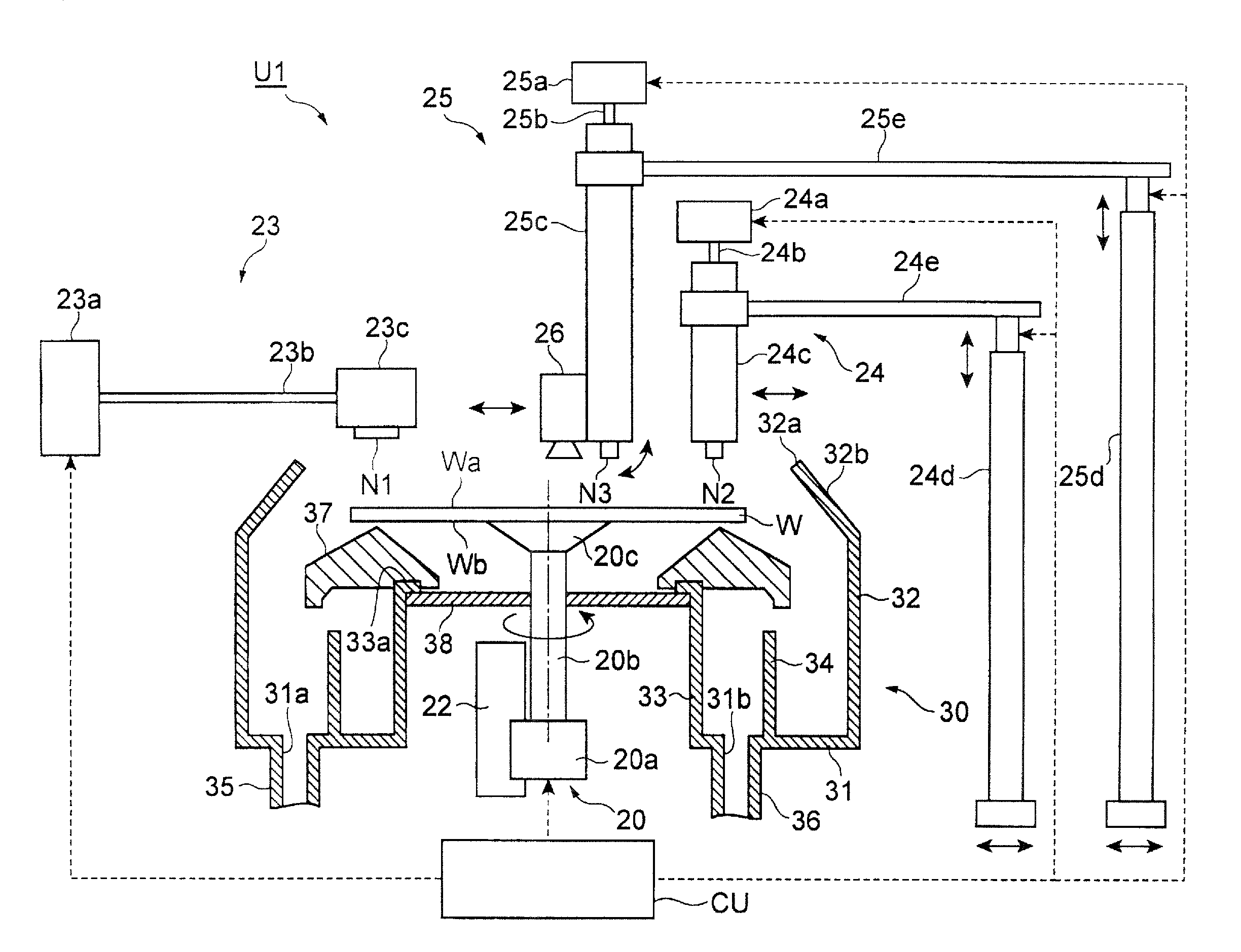
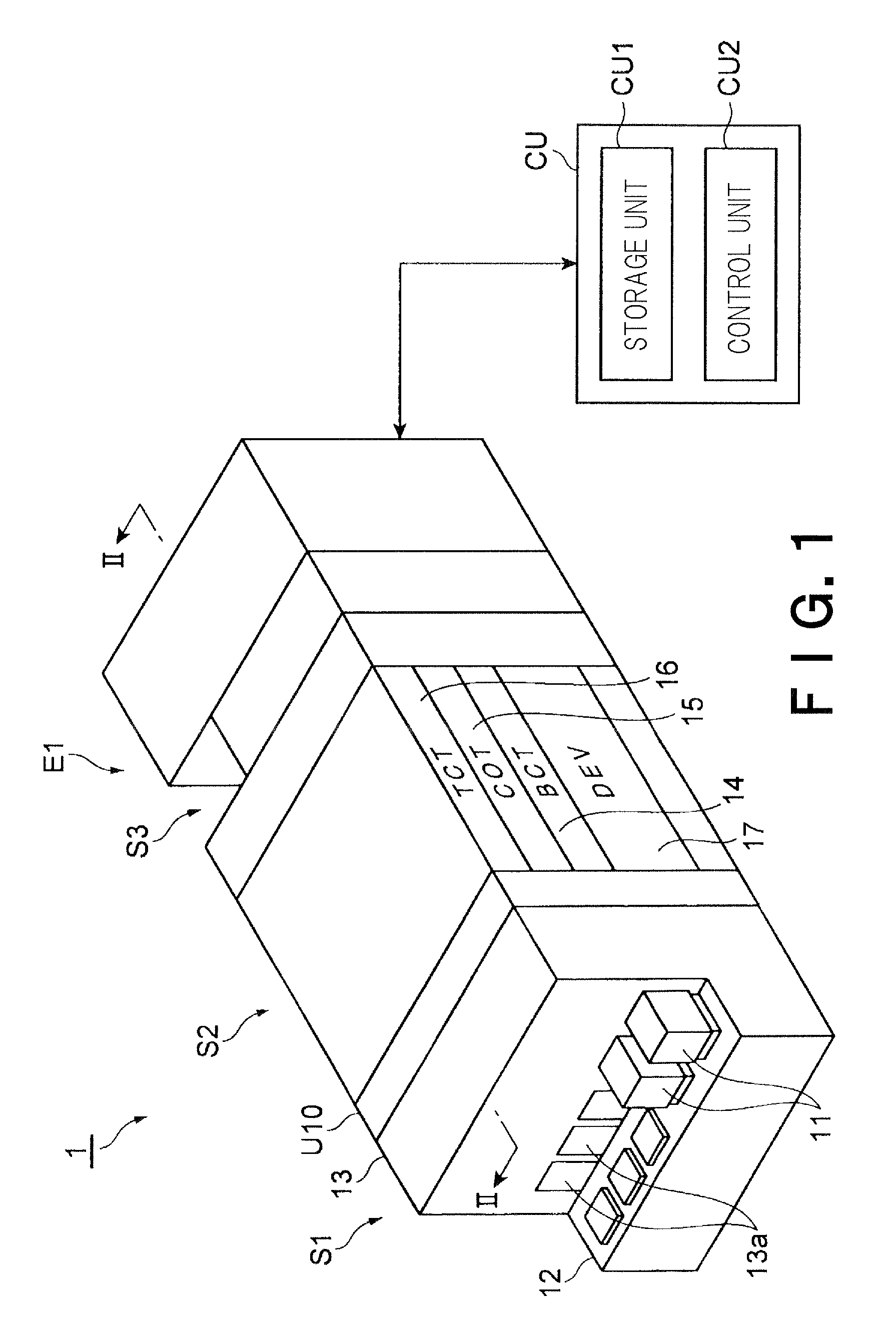
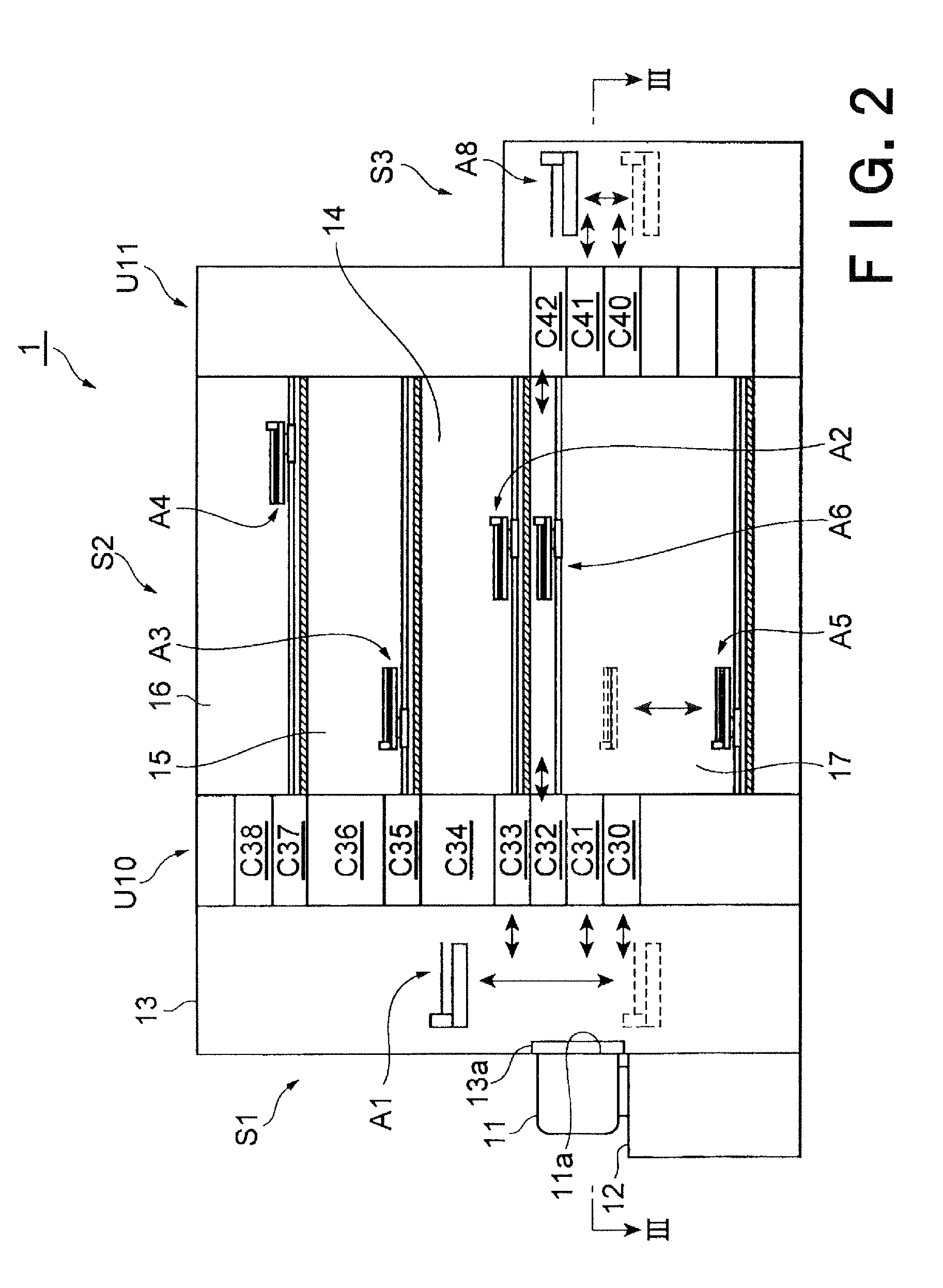
[0029]A schematic structure of the coating / developing apparatus 1 shown in FIGS. 1 to 3 is described. The coating / developing apparatus 1 is configured to coat a surface of a wafer (substrate) W with a resist material to form a resist film, before an exposure process performed by an exposure apparatus E1. The coating / developing apparatus 1 is configured to develop the resist film formed on the wafer W, after the exposure process to be performed by the exposure apparatus E1. In this embodiment, the wafer W has a discoid shape, but a partially cut circular wafer or a wafer ha...


PUM

PropertyMeasurementUnit
ejection timeaaaaaaaaaa

Abstract

A substrate cleaning method includes: a first step in which a cleaning liquid is ejected from a nozzle N2 to a central portion of a wafer W; a second step in which a dry gas is ejected from a nozzle N3 to the central portion of the wafer W to form a dry area; a third step in which the cleaning liquid is ejected from the nozzle N2 while the nozzle N2 is moved from a central side of the wafer W to a peripheral side thereof; a fourth step in which a width of an intermediate area generated between a wet area and the dry area is acquired; and a fifth step in which, when the width of the intermediate area exceeds a predetermined threshold value, a process parameter is changed such that the width of the intermediate area becomes the threshold value or less.

Description

CROSS REFERENCE TO RELATED APPLICATIONS[0001]This application is based upon and claims the benefit of priority from the prior Japanese Patent Application No. 2014-002413 filed on Jan. 9, 2014 the entire contents of which are incorporated herein by reference.FIELD OF THE INVENTION[0002]The present invention relates to a substrate cleaning method, a substrate cleaning apparatus, and a computer-readable storage medium.BACKGROUND ART[0003]In a recent a micro-process, an irregular pattern (e.g., resist pattern) is generally formed on a substrate (e.g., semiconductor wafer) by means of a photolithographic technique. Specifically, the irregular pattern is formed by a coating step for coating a substrate with a resist material to form a resist film, an exposure step for exposing the resist film, and a developing step for developing the exposed resist film.[0004]The developing step includes a cleaning process in which a substance of a dissolved resist (dissolved resist substance), which has ...

Claims


Application Information

Patent Timeline
Patent Type & Authority Patents(United States)
IPC IPC(8): B08B7/00G03F7/42H01L21/67
CPCH01L21/67051G03F7/422B08B3/024G01B11/02G03F7/70925
Inventor UEMURA, RYOICHITAKIGUCHI, YASUSHI
Owner TOKYO ELECTRON LTD
Why Eureka
Try Eureka