Mowing machine brake apparatus with slideable engagement

Active Publication Date: 2017-02-02
PARKER HANNIFIN CORP
View PDF0 Cites 4 Cited by
  • Summary
  • Abstract
  • Description
  • Claims
  • Application Information

AI Technical Summary

Benefits of technology

[0006]The present invention provides a brake apparatus that affords one or more advantages over conventional vehicles, such as mowing machines. The brake apparatus restricts rotation of a rotatable member of a vehicle, such as an output shaft of a mowing machine. The brake apparatus includes a mechanism that does not require a gear reduction and may greatly lessen forces necessary to

Problems solved by technology

In some brake assemblies, a locking mechanism mechanically interferes with the hub to restrict or prevent movement and provide the required brake torque.
Known brake assemblies typically require a gear reduction to amplify the brake torque, or may require larger than desired actuation forces to engage the hub.
This is particu

Method used


Image

  • Mowing machine brake apparatus with slideable engagement
  • Mowing machine brake apparatus with slideable engagement
  • Mowing machine brake apparatus with slideable engagement

Examples


Embodiment Construction

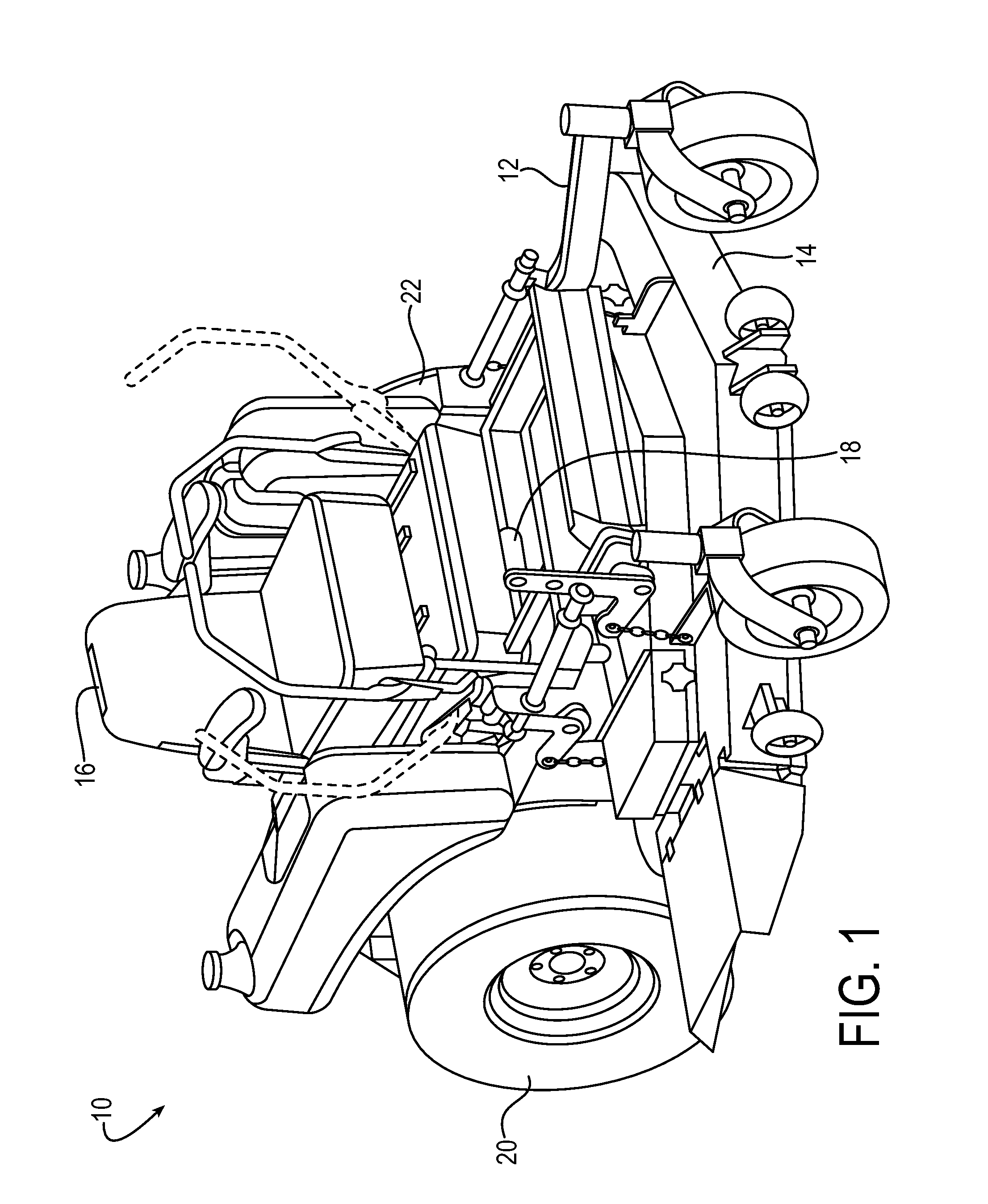
[0068]The principles of the present application have particular application to mowers, such as zero-turn-radius mowers, and thus will be described below chiefly in this context. It will of course be appreciated and also understood that the principles of the invention may be useful in other vehicles, such as vehicles utilizing mechanical, hydrostatic, hydraulic, or electric drive systems, or with any equipment requiring restriction of rotation of a component, such as upon demand.

[0069]Referring now to the drawings in detail, and initially to FIG. 1, an exemplary zero-turn-radius mower 10 is illustrated. The mower 10 includes a frame 12, a mower deck 14 supported by the frame 12 for mowing grass, an operator seat 16, and a plurality of controls 18 for operating the mower 10. A rear mounted engine (not shown) mounted to the frame 12 behind the seat 16 provides power to a hydraulic axle combination mounted to the frame 12, the hydraulic axle combination including hydrostatic transmissio...


PUM


Abstract

A brake apparatus for a mowing machine that includes a brake gear operatively rotatable with a rotatable member and a lock assembly for meshing with the brake gear to restrict rotation of the brake gear. A guide rail assembly is fixable relative to a support for supporting the rotatable member for rotation. The guide rail assembly guides a lock assembly movable between an unlocked arrangement and a locked arrangement. An actuator plate and the guide rail assembly jointly engage the lock assembly to effect meshing and unmeshing of at least one engagement member of the lock assembly, such as a roller or a jaw member, with the brake gear. The actuator plate is selectively rotatable about an axis of rotation of the brake gear relative to the guide rail assembly, where rotation of the actuator plate effects movement of the lock assembly between the unlocked and locked arrangements.

Description

FIELD OF INVENTION[0001]The present invention relates generally to transmissions, and more particularly to brake assemblies, also herein referred to as brake apparatuses, for transmissions used in vehicles, such as mowing machines.BACKGROUND[0002]Hydrostatic transmissions have many uses, including the propelling of vehicles, such as mowing machines. A typical hydrostatic transmission system includes a variable displacement hydraulic pump connected in a closed hydraulic circuit with a fixed or variable displacement hydraulic motor. The closed hydraulic circuit includes a first conduit connecting the main pump outlet with the motor inlet and a second conduit connecting the motor outlet with a pump inlet. Either of these conduits may be the high pressure line depending upon the direction of pump displacement from neutral.[0003]For most applications, the pump is driven by a prime mover, such as an internal combustion engine or an electrical motor, at a certain speed in a certain directi...

Claims


Application Information

Patent Timeline
IPC IPC(8): A01D69/10F16D63/00
CPCF16D63/006A01D69/10
Inventor GILBERT, KENNETH TODDHEATHCOAT, JR., DAVID M.RICHARDSON, JASON S.JOHNSON, TAYLOR
Owner PARKER HANNIFIN CORP
Why Eureka
Try Eureka