

Vehicle Drive Control Apparatus and Speed Control Method
a technology of vehicle drive and control apparatus, which is applied in the direction of process and machine control, transportation and packaging, instruments, etc., can solve the problems of affecting the comfort of riding for the occupant, affecting the speed of vehicle movement, so as to improve convenience and a sense of security
- Summary
- Abstract
- Description
- Claims
- Application Information
AI Technical Summary
Benefits of technology
Problems solved by technology
Method used
Image

Examples
first embodiment
[0036]First, a first embodiment to be an example of the present invention will he described using FIGS. 1 to 5.
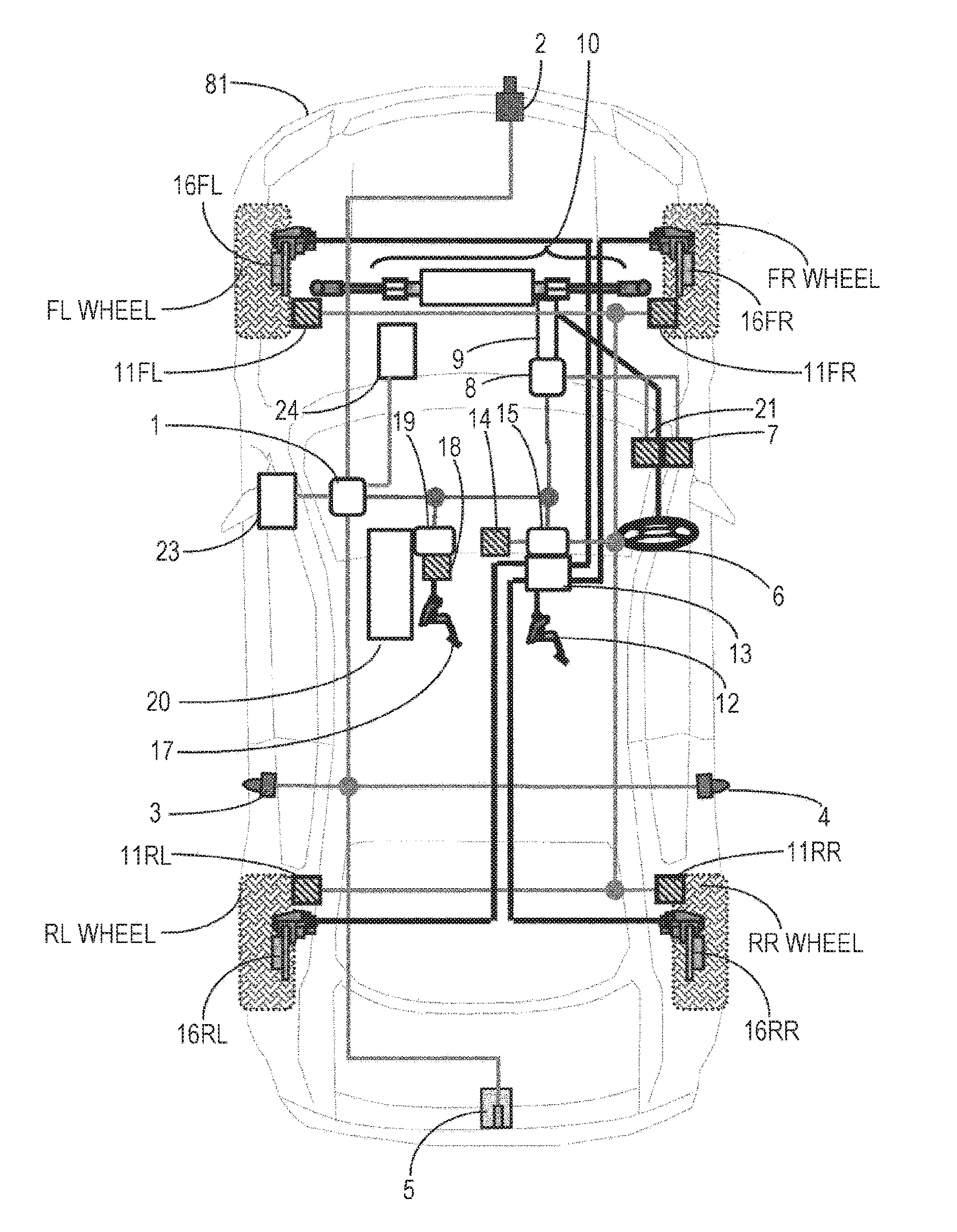
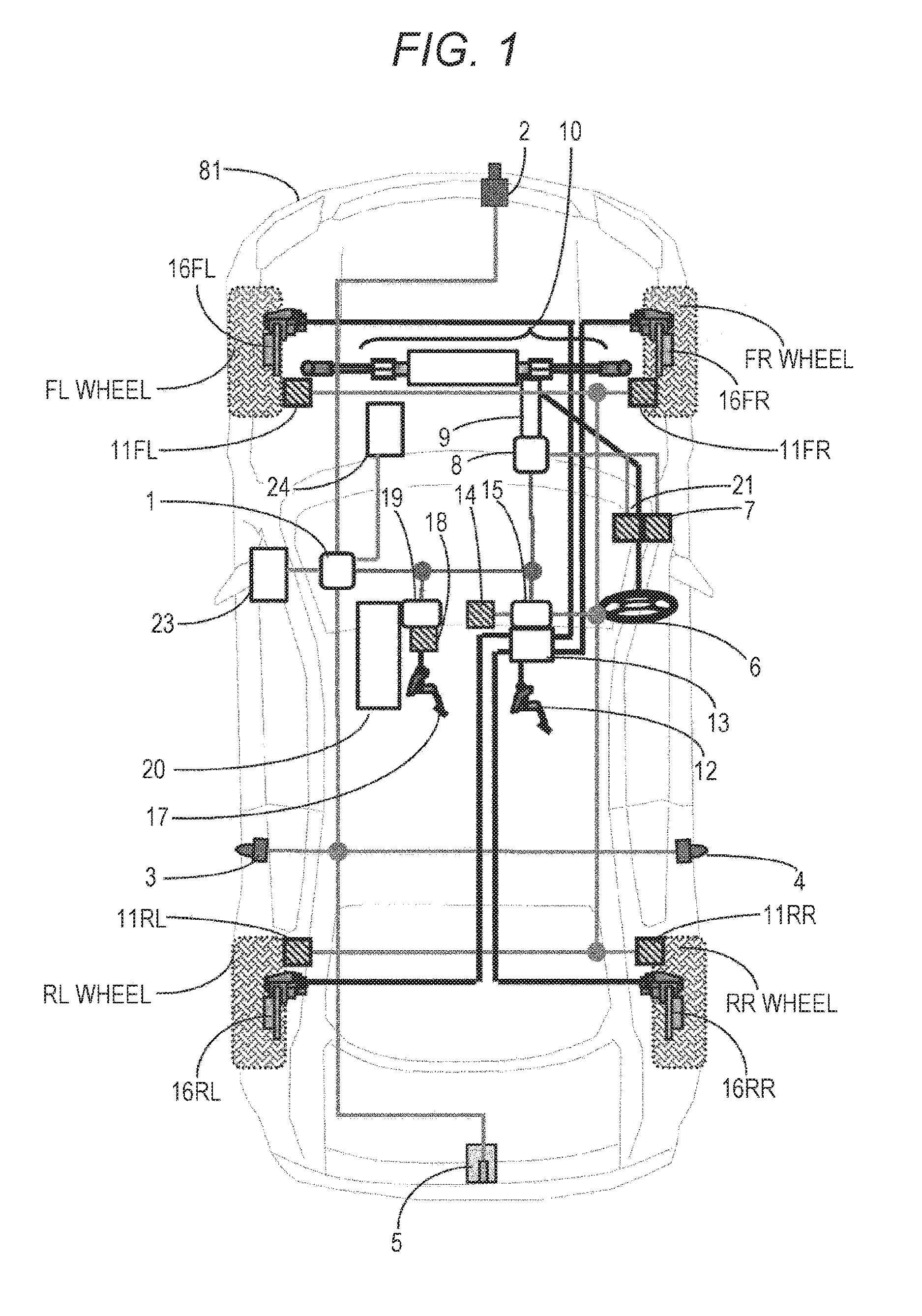
[0037]FIG. 1 is a diagram illustrating an entire configuration of a vehicle 41 on which a vehicle drive control apparatus 1 according to the first embodiment is mounted. An FL wheel, an FR wheel, an RL wheel, and an RR wheel mean a front left wheel, a front rear wheel, a rear left wheel, and a rear right wheel, respectively.
[0038]The vehicle 41 includes a vehicle drive control apparatus 1 that operates command values for a steering control mechanism 10 to control a travelling direction of the vehicle, a brake control mechanism 13, and a throttle control mechanism 20, on the basis of information of sensors 2, 3, 4, and 5 to recognize an external world. In addition, the vehicle 41 includes a steering control device 8 that controls the steering control mechanism. 10, on the basis of the command value from the vehicle drive control apparatus 1, a braking control device 15 that ...
second embodiment
[0067]Next, a second embodiment to be an example of the present invention will be described using FIGS. 6 to 20C. Descriptions for the parts similar to the first embodiment described above are omitted.
[0068]In the first embodiment, a speed change is performed on the basis of a minimum distance of an own vehicle 41 and a speed change induction obstacle 43. However, in actuality, there is the possibility that the own vehicle 41 passes by the speed change induction obstacle 43 before a movement vector of the moving object 42 changes, even when both the moving object 42 and the speed change induction obstacle 43 are detected. In this case, making a speed plan where the own vehicle 41 decelerates whenever both the moving object 42 and the speed change induction obstacle 43 are detected may impair quick transportability for an occupant. Therefore, it may be determined whether there is the possibility that the own vehicle 41 and the moving object 42 contact each other in the future by pred...
third embodiment
[0120]Next, a third embodiment to be an example of the present invention will be described using FIGS. 21 to 24C. Descriptions for the parts similar to the first or second embodiment described above are omitted.
[0121]In the first and second embodiments, a speed change is performed only when both a moving object 42 and a speed change induction obstacle 43 exist and the speed change is not performed when only the moving object 42 exists. As a result, even when an own vehicle 41 passes through the immediate vicinity of the moving object 42, the own vehicle 41 does not decelerate and it may lead to a sense of discomfort or a sense of uneasiness for an occupant.
[0122]In addition, a prediction movement path 46 is only a prediction. Even in the case where the moving object 42 induces a speed vector change against the prediction, it is preferable to use a speed plan to prevent a contact with the own vehicle 41 together. Therefore, in the present invention, even in the case where only the mo...
PUM
 Abstract
Description
Claims
Application Information