

Printing on Cylindrical Objects
a cylindrical object and printing technology, applied in the field of printing on cylindrical objects, can solve the problems of limiting the rate at which cylindrical objects can be printed, the inability to form the entire image, and the maximum rate at which a single printhead can print, and achieve the effect of simple calibration process
- Summary
- Abstract
- Description
- Claims
- Application Information
AI Technical Summary
Benefits of technology
Problems solved by technology
Method used
Image

Examples
Embodiment Construction
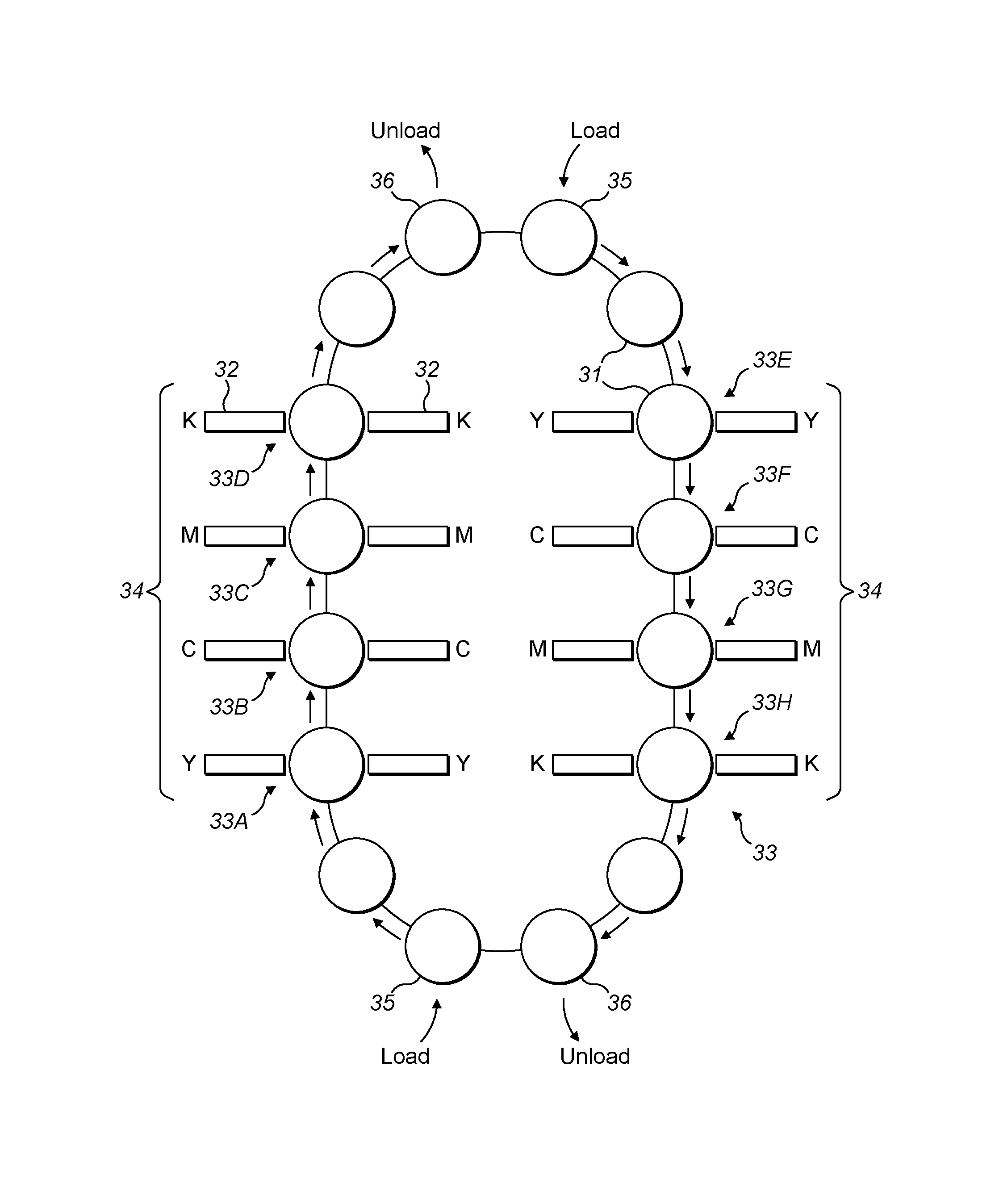
[0041]The present invention provides an apparatus and method for digitally printing on cans 31 or other cylindrical objects 31 which allows a high throughput whilst maintaining optimum print quality.
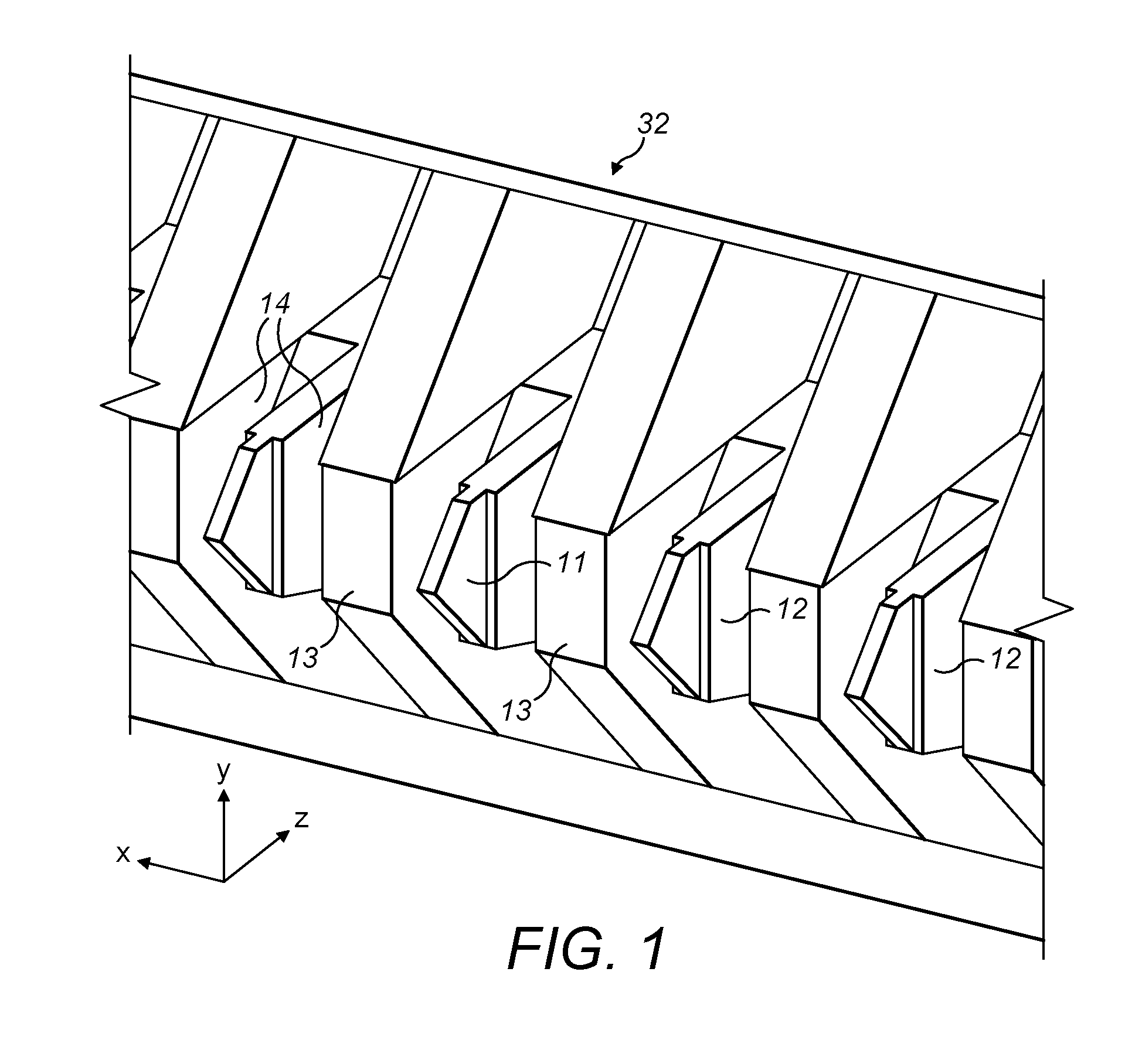
[0042]FIG. 1 shows a printhead 32 comprising a linear array of ejectors 11, each of which can be made to eject a volume of ink with the application of an electric field between the ejection location and the substrate. Each ejector 11 is shaped with a narrow tip, around which ink flows, providing a highly localised ejection location. An ejection cell is defined by two dividing walls 13, also called a cheek, between which lies a central upstand 12. In each cell, ink flows in the two pathways 14, one on each side of the ejection upstand 12 and in use the ink meniscus is pinned between the top of the cheeks and the top of the ejection upstand. In this geometry the positive direction of the z-axis is defined as pointing from the substrate towards the printhead (typically along the shortest di...
PUM
 Abstract
Description
Claims
Application Information