
Comprehensive fitness equipment leg press
a fitness equipment and comprehensive technology, applied in the field of fitness equipment, can solve the problems of user injury, excessive bulky and heavy exercise equipment, insufficient exercise amount,
- Summary
- Abstract
- Description
- Claims
- Application Information
AI Technical Summary
Benefits of technology
Problems solved by technology
Method used
Image

Examples
Embodiment Construction
[0033]Hereinafter, technical configuration of the present invention is described in detail referring to the drawings attached.
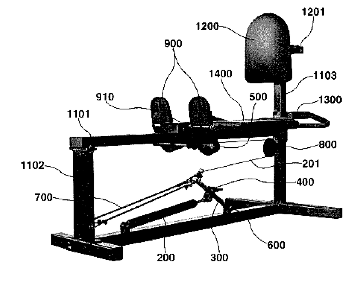
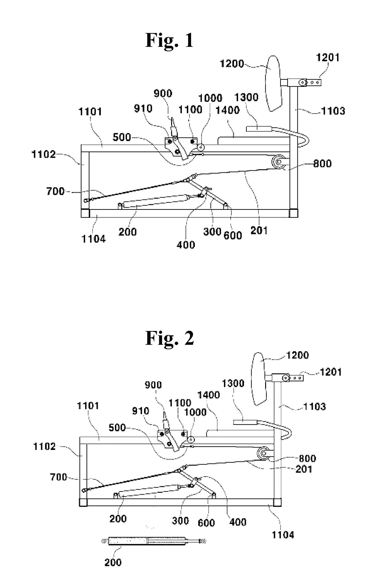
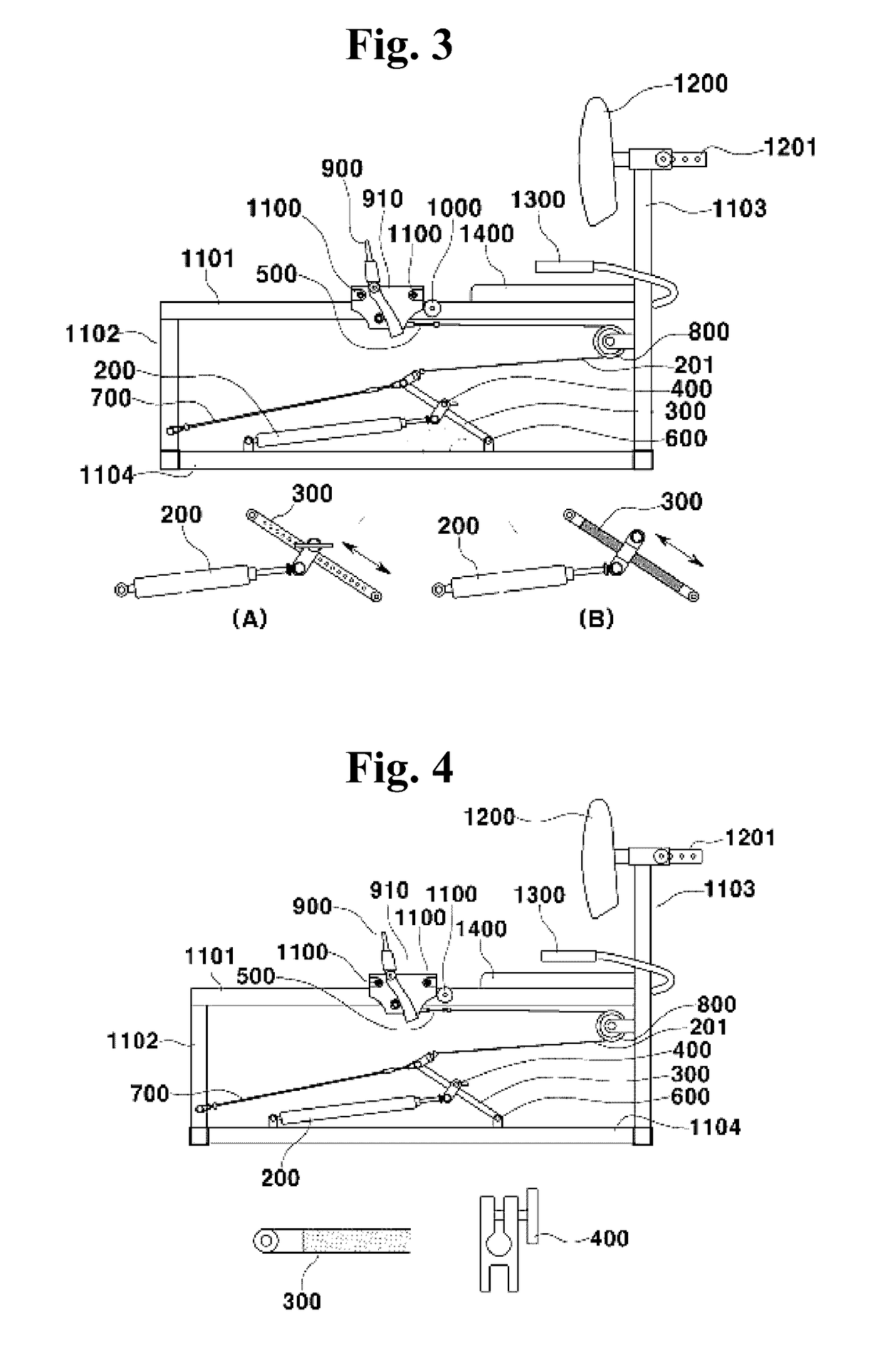
[0034]FIG. 1 shows a right side view of a leg press, fitness equipment of the present invention, a footrest (910) having a footrest frame (900) installed to move back and forth on a central frame (1101) connected to a front post frame (1102) and a rear post frame (1103) is installed.
[0035]An end of a wire (201) is connected to the footrest frame (910) having the footrest (900)installed on the central frame (1101), and another end of the wire (201) is connected to an upper end of a weight adjusting bar (300) capable of adjusting tension of the footrest (910).
[0036]An end of a rod of the hydraulic cylinder (200) is coupled to a portion of the weight adjusting bar (300) in length direction thereof with a fixing band (400) to generate tension on the wire (201) connected to the footrest frame (910).
[0037]A wire roller (800) is installed on a side of the rear post ...
PUM
 Abstract
Description
Claims
Application Information