Centrifugal ceiling fan

a ceiling fan and centrifugal technology, applied in the field of ceiling fans, can solve the problems of unventilated space, uneven distribution of air throughout the room, and unoccupied space of the paddles

Active Publication Date: 2017-08-17
SECTAR SOLUTIONS
View PDF10 Cites 20 Cited by
  • Summary
  • Abstract
  • Description
  • Claims
  • Application Information

AI Technical Summary

Benefits of technology

[0011]In one aspect, there is provided a centrifugal ceiling fan comprising a casing defining a top, a side and a bottom; an air inlet provided at the top of the casing; a centrifugal propeller configured to rotate about a rotation axis; a motor operatively connected to said centrifugal propeller; an air outlet comprising a first passage for pushing air from the side, and a second passage for pushing air from the bottom; the air outlet comprising a central dome, the central dome coil being adapted to distribute a flow of air between the first passage and the second passage to a desired proportion; wherein rotation of the centrifugal propeller causes air to be received from said air inlet and to be pushed from said air outlet in substantially all directions between the first direction and the second direction for evenly ventilating a room in which the centrifugal ceiling fan is installed.

Problems solved by technology

This type of fans has several problems.
One of the problems is the uneven distribution of air throughout the room.
Therefore, the area outside the radius of the paddles remains unventilated.
Other problems associated with axial fans include the space occupied by the paddles and the safety concerns due to the fact that the paddles are exposed as they rotate.
Thus, to obtain the same ventilation results, the rotation speed has to be increased, which results in an increase in energy consumption and noise.

Method used


Image

  • Centrifugal ceiling fan
  • Centrifugal ceiling fan
  • Centrifugal ceiling fan

Examples


Embodiment Construction

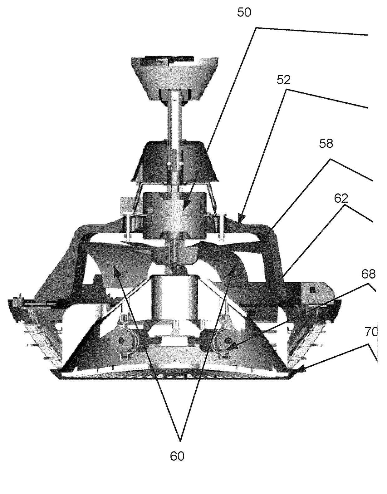
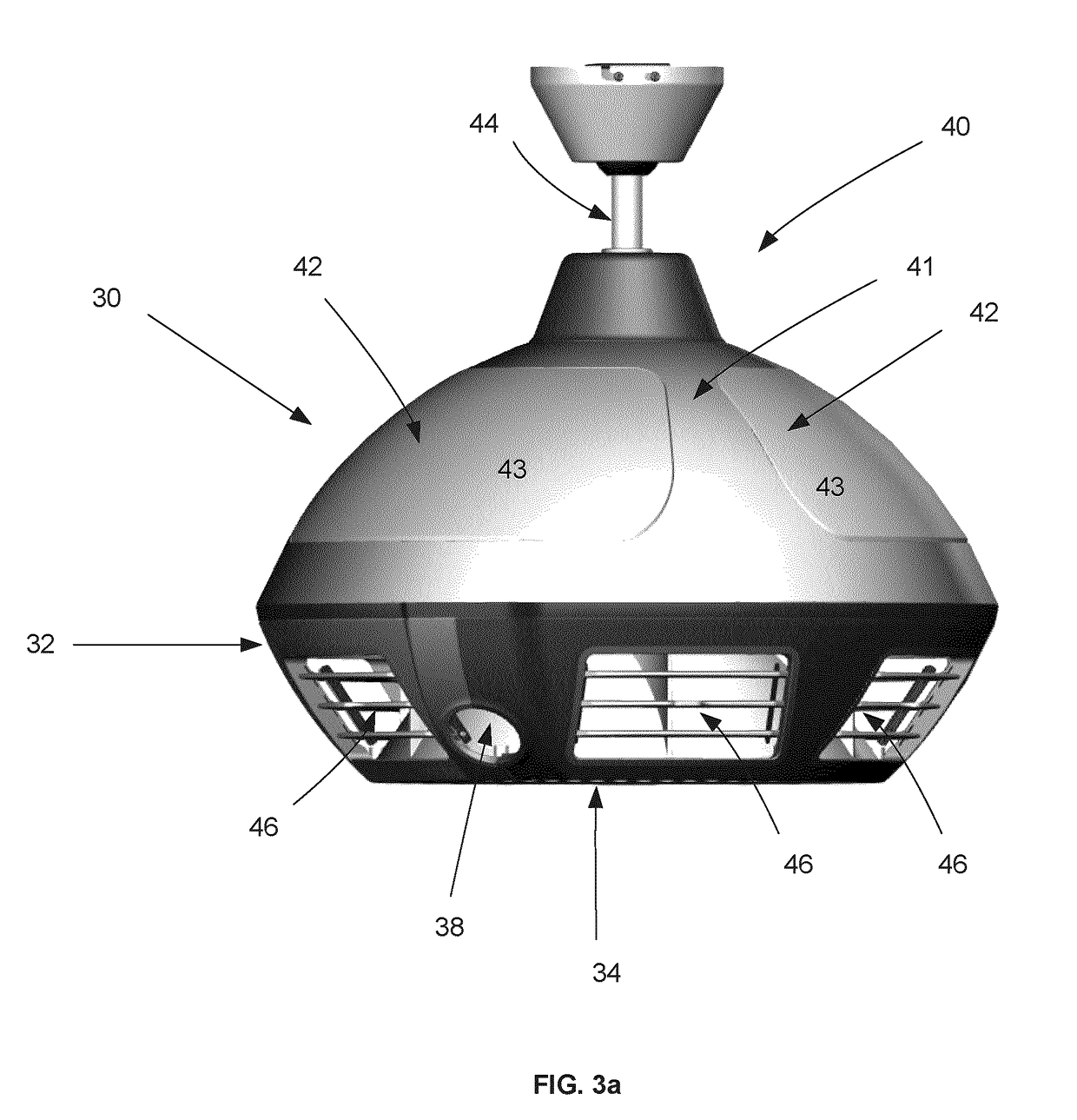
[0048]The embodiments describe a centrifugal ceiling fan adapted to evenly ventilate and heat its surrounding area. The fan comprises a casing defining a top, a side, and a bottom. The air inlet is provided in the top and the air outlet comprises a first passage provided in the side and a second passage provided in the bottom. The air outlet comprises a central dome for regulating the flow of air between the first passage and the second passage to a desired proportion. The central dome comprises a plurality of openings shaped and dimensioned to define the amount and the direction of the air flow pushed downward. The fan comprises a centrifugal propeller having blades which are curved and have a variable width such that rotation of the centrifugal propeller causes air to be received from said air inlet and to be pushed from said air outlet in substantially all directions between the first direction and the second direction. A heat source may be provided within the dome for heating ai...


PUM


Abstract

A centrifugal ceiling fan adapted to evenly ventilate and heat its surrounding area. The fan comprises a casing defining a top, a side, and a bottom. The air inlet is provided in the top and the air outlet comprises a first passage provided in the side and a second passage provided in the bottom, and a central dome for regulating the flow of air between the first passage and the second passage to a desired proportion. The fan comprises a centrifugal propeller having blades which are curved and have a variable width such that rotation of the centrifugal propeller causes air to be received from said air inlet and to be pushed from said air outlet in substantially all directions between the first direction and the second direction. The dome comprises a heat source for heating air pushed downward from the bottom. Whereby, unheated air is pushed sideways and heated air is pushed downward and for evenly ventilating and heating a room in which the centrifugal ceiling fan is installed.

Description

RELATED APPLICATIONS[0001]The present application claims priority from U.S. Provisional Application No. 62 / 036,689 filed on Aug. 13, 2014, which is incorporated herein by reference in its entirety.BACKGROUND[0002](a) Field[0003]The subject matter disclosed generally relates to ceiling fans.[0004](b) Related Prior Art[0005]FIG. 1 illustrates a conventional axial ceiling fan 20. The ceiling fan 20 includes a plurality of paddles 22, a lamp 24, a motor 26 for turning the paddles 22, and attachment means 28 for attaching the ceiling fan 20 to the roof.[0006]This type of fans has several problems. One of the problems is the uneven distribution of air throughout the room. The paddles are mounted vertically to the axis of rotation and push the air downward in the same direction as the axis of rotation. Therefore, the area outside the radius of the paddles remains unventilated. Other problems associated with axial fans include the space occupied by the paddles and the safety concerns due to...

Claims


Application Information

Patent Timeline
Patent Type & Authority Applications(United States)
IPC IPC(8): F04D25/08F24F7/007F04D29/58F04D17/16F04D29/42
CPCF04D25/088F04D17/16F24F7/007F04D29/582F04D29/4226F04D19/002F04D29/541F24F1/0071F24F8/96
Inventor SECCARECCIA, ALESSANDRO
Owner SECTAR SOLUTIONS
Why Eureka
Try Eureka