Fuel cutoff valve

Active Publication Date: 2010-03-25
TOYODA GOSEI CO LTD
View PDF7 Cites 3 Cited by
  • Summary
  • Abstract
  • Description
  • Claims
  • Application Information

AI Technical Summary

Benefits of technology

[0010]In the fuel cutoff valve according to this aspect of the invention, the casing including the valve chest to receive the float therein has the vent hole, which is formed for ventilation of the air between the valve chest and the fuel tank. The vent hole has the small diameter and is provided in the bottom area of the bottomed recess formed as the concave in the outer circumferential wall of the valve chest. The bottomed recess is located between the position of thermally welding the cover member to the upper wall face of the fuel tank with molten resin and the opening of the vent hole. Even if the molten resin flows from the position of thermal weld, the presence of the bottomed recess keeps the molten resin therein. This arrangement effectively prevents the potential blockage of the vent hole by the molten resin used for thermally welding the cover member to the upper wall face of the fuel tank, while assuring the smooth ventilation of the air between the valve chest and the fuel tank via the vent hole.
[0011]The small-diameter vent hole formed in the bottom area of the bottomed recess has the following effects. Many components of the fuel cutoff valve including the cover member, the casing, and the float are made of a resin material, with a view to facilitating the thermal welding to the fuel tank and attaining weight reduction. The respective components of the fuel cutoff valve are molded with dies. The procedure of molding the casing with small-diameter vent holes sets a split die to form a cavity around a core die used for defining the valve chest. The split die has vent hole-forming pins used for formation of the respective vent holes. The small-diameter vent hole-forming pin is naturally used to form the small-diameter vent hole. The small-diameter vent hole-forming pin is readily bent by the pressure of resin injection into the cavity. The bent pin leads to formation of burr on the periphery of the opening of the vent hole. Troublesome removal of the burr is then required. In order to prevent the burr formation, the careful pressure control of resin injection is required to the level of ensuring no bend of the pin. This pressure control is al

Problems solved by technology

Continued fuel supply in this blockage state increases the internal pressure of the fuel tank and causes blow-off of the fuel.
This may interfere wit

Method used


Image

  • Fuel cutoff valve
  • Fuel cutoff valve
  • Fuel cutoff valve

Examples


Embodiment Construction

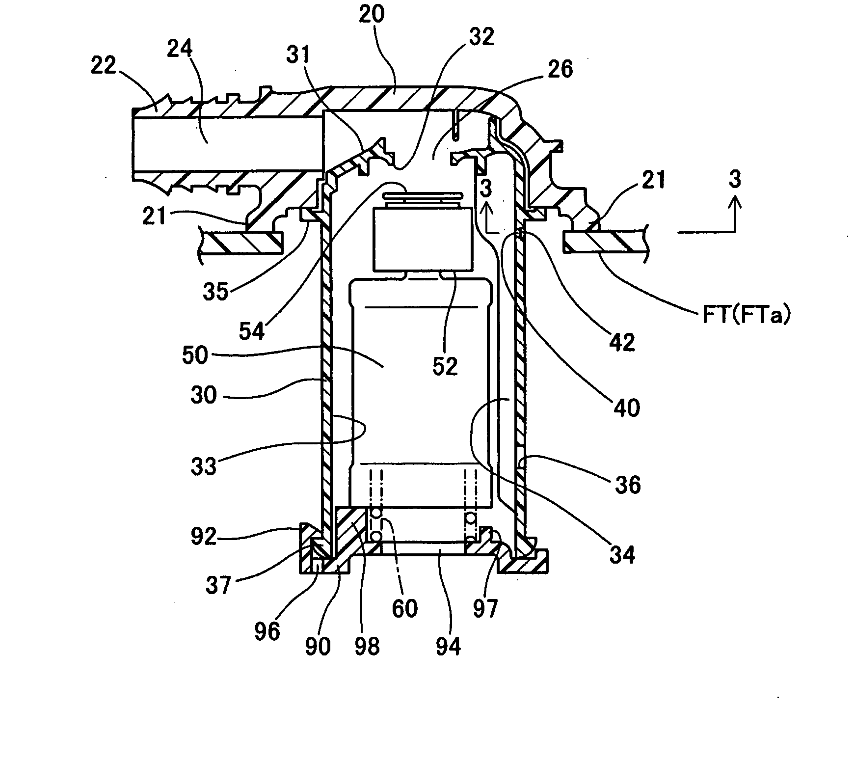
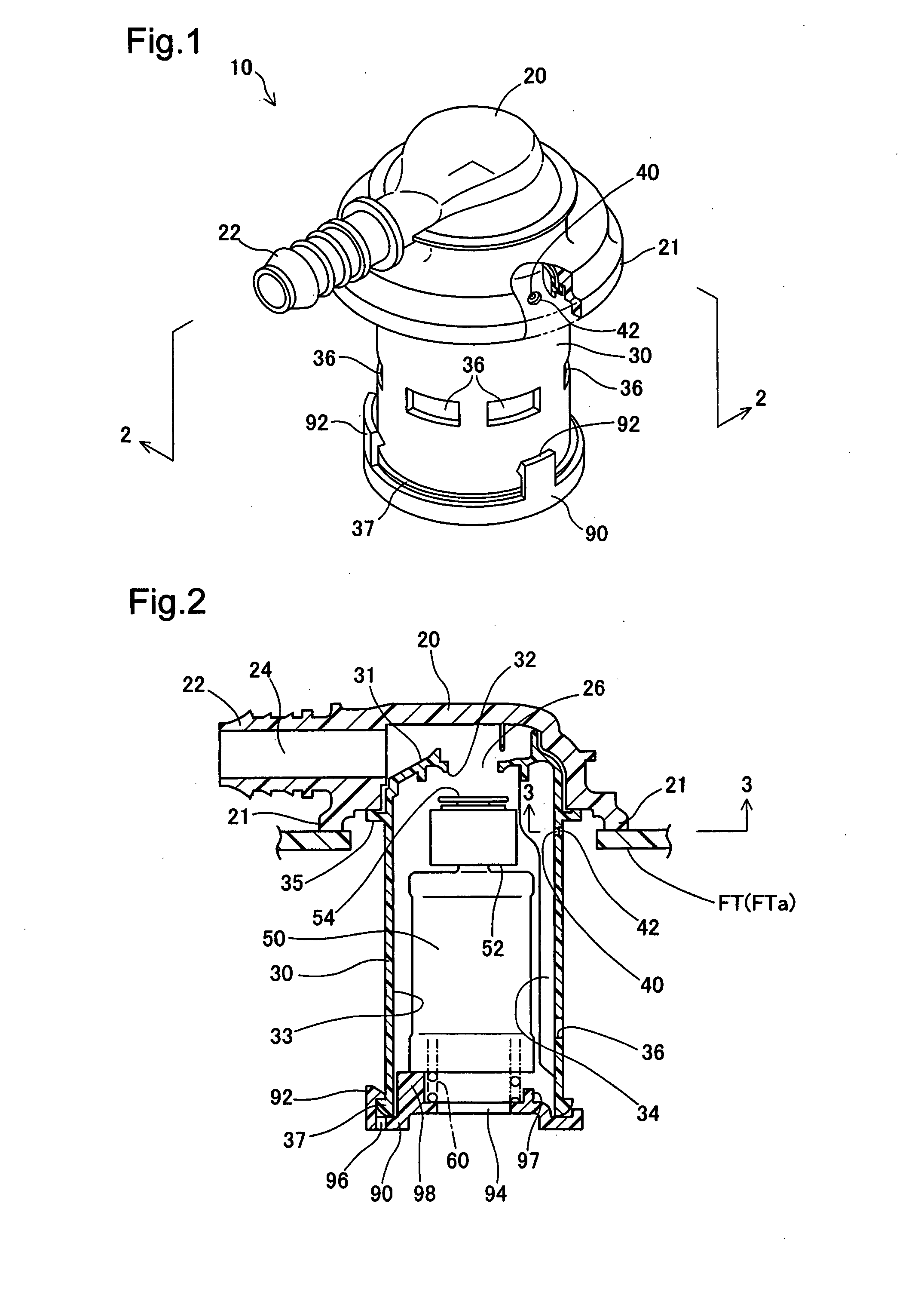
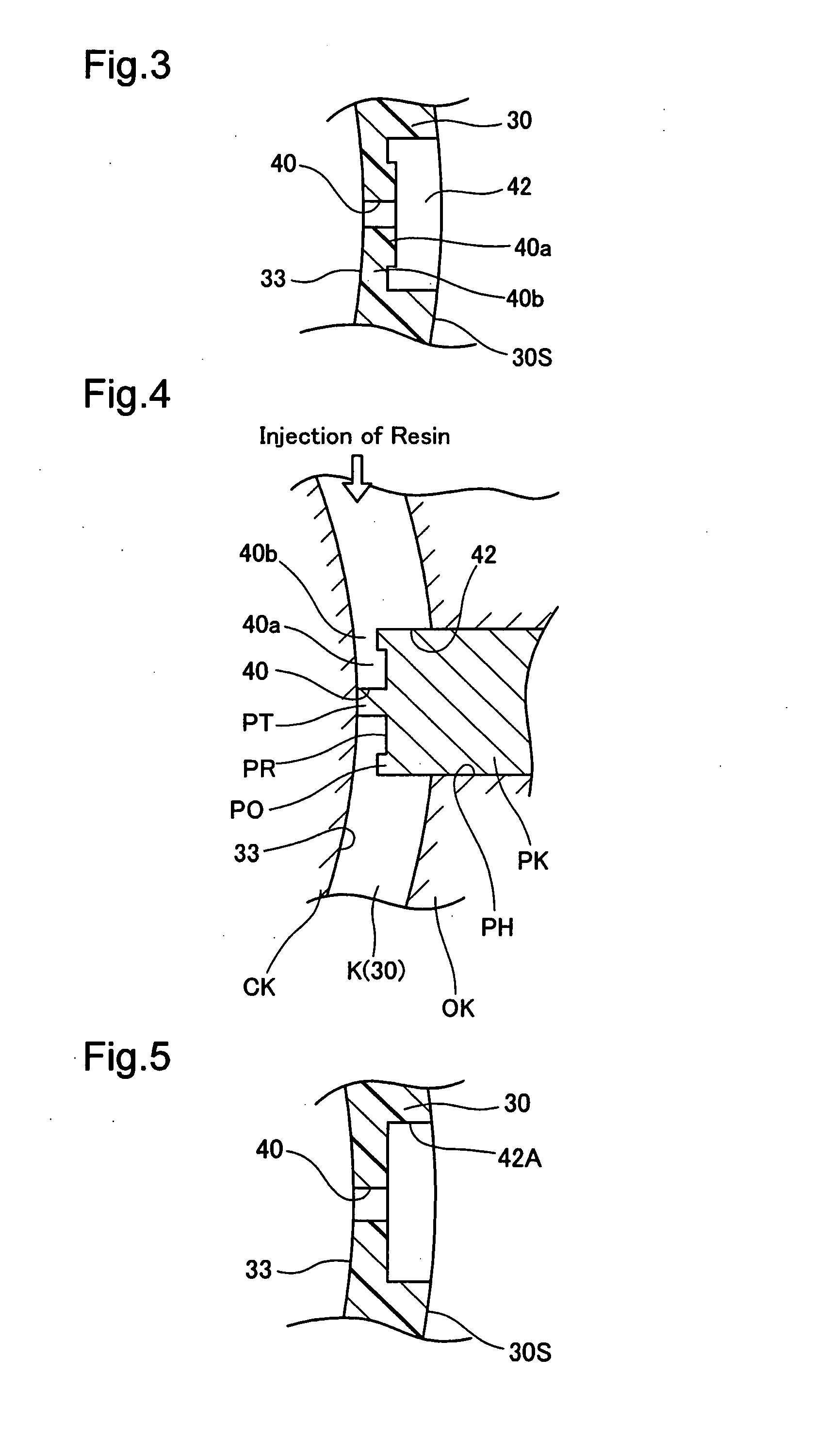
[0020]In order to clarify the structures, the features, the characteristics, and the functions of the invention, some modes of carrying out the invention are described below with reference to the accompanied drawings. FIG. 1 is a perspective view schematically showing the appearance of a fuel cutoff valve 10 in one embodiment of the invention. FIG. 2 is a vertical sectional view showing the main part of the fuel cutoff valve 10, taken on a 2-2 line of FIG. 1. FIG. 3 is a cross sectional view showing a casing 30, taken on a 3-3 line of FIG. 2.

[0021]As illustrated, the fuel cutoff valve 10 is attached to an upper portion of a fuel tank FT. The fuel tank FT is made of a composite resin material containing polyethylene in its outer surface layer and has a mounting hole FTb formed in an upper tank wall FTa to receive the fuel cutoff valve 10 inserted and fitted therein. As the fuel cutoff valve 10 is set in the mounting hole FTb, a lower end section 21 of a cover member 20 is thermally w...


PUM


Abstract

In a fuel cutoff valve 10, a casing 30 including a valve chest 33 is fastened to a cover member 20 thermally welded to an upper tank wall FTa of a fuel tank FT. A float 50 is located in the valve chest 33 of the casing 30. The casing 30 has bottomed recesses 42 formed as concaves in an outer circumferential wall of the valve chest 33, and vent holes 40 provided at respective bottom areas of the bottomed recesses 42. Each of the vent holes 40 is a through hole of a small diameter, which is determined to be sufficient for ventilation of the fuel vapor in the valve chest 33. The vent hole 40 has a short dimension by the depth of the bottomed recess 42.

Description

CROSS-REFERENCE TO RELATED APPLICATIONS[0001]The present application claims the priority based on Japanese Patent Application No. 2008-240287 filed on Sep. 19, 2008, the disclosure of which is hereby incorporated by reference in its entirety.BACKGROUND[0002]1. Technical Field[0003]The present invention relates to a fuel cutoff valve attached to an upper portion of a fuel tank and configured to open and close a connection conduit for connecting and disconnecting inside of the fuel tank with and from outside.[0004]2. Description of the Related Art[0005]In a fuel cutoff valve designed to discharge the fuel vapor out of a fuel tank, as the fuel is flowed into a valve chest for receiving a float therein in response to a variation of the fuel level during a vehicle drive or in response to a rise of the fuel level during fuel supply, the float lifts up to block the discharge of the fuel vapor. Continued fuel supply in this blockage state increases the internal pressure of the fuel tank and...

Claims


Application Information

Patent Timeline
IPC IPC(8): B65D88/38
CPCF16K24/044Y10T137/3099
Inventor NISHI, HIROSHIKITO, HIROAKI
Owner TOYODA GOSEI CO LTD
Why Eureka
Try Eureka