Side lock sleeve assembly

a side lock and assembly technology, applied in the direction of rod connections, fastening means, stands/trestles, etc., can solve the problems of sleeve and basic tube wobbling, and achieve the effect of eliminating prior drawbacks, light weight, and stable engagemen

Active Publication Date: 2018-05-10
LIN CHIEN TING
View PDF0 Cites 1 Cited by
  • Summary
  • Abstract
  • Description
  • Claims
  • Application Information

AI Technical Summary

Benefits of technology

[0011]To be more specific, in the side lock sleeve assembly of the present invention, since the threaded fitting portion is formed on the outer surface of the first tube and the threaded fitting portion complementing with the extension section of the fastening screw, a greater engagement contact area is formed among the fastening screw, the first tube and the sleeve after assembly, thereby providing a stable engagement thereamong and eliminating prior drawbacks. Note the first tube employed in the tube assembly of the present invention is durable and light in weight, and there is no need to do the aligning of the fastening screw relative to the hole during the fixing process, thereby providing swift assembly of products and is suitable for mass production process.

Problems solved by technology

Such type of fixing method is only suitable for the basic tube having a relative wall thickness and in case of the basic tube with thin wall thickness, after the fixing operation, wobbling may result between the sleeve and the basic tube.
Due to advance of technology, the wall confining the tube is constructed thinner but stronger in rigidity and it is noted that only the fixing means remain unchanged presently and are not suitable for the presently available tube assemblies, the conventional fixing means are intended for tubes with relatively thick walls.

Method used


Image

  • Side lock sleeve assembly
  • Side lock sleeve assembly
  • Side lock sleeve assembly

Examples


first embodiment

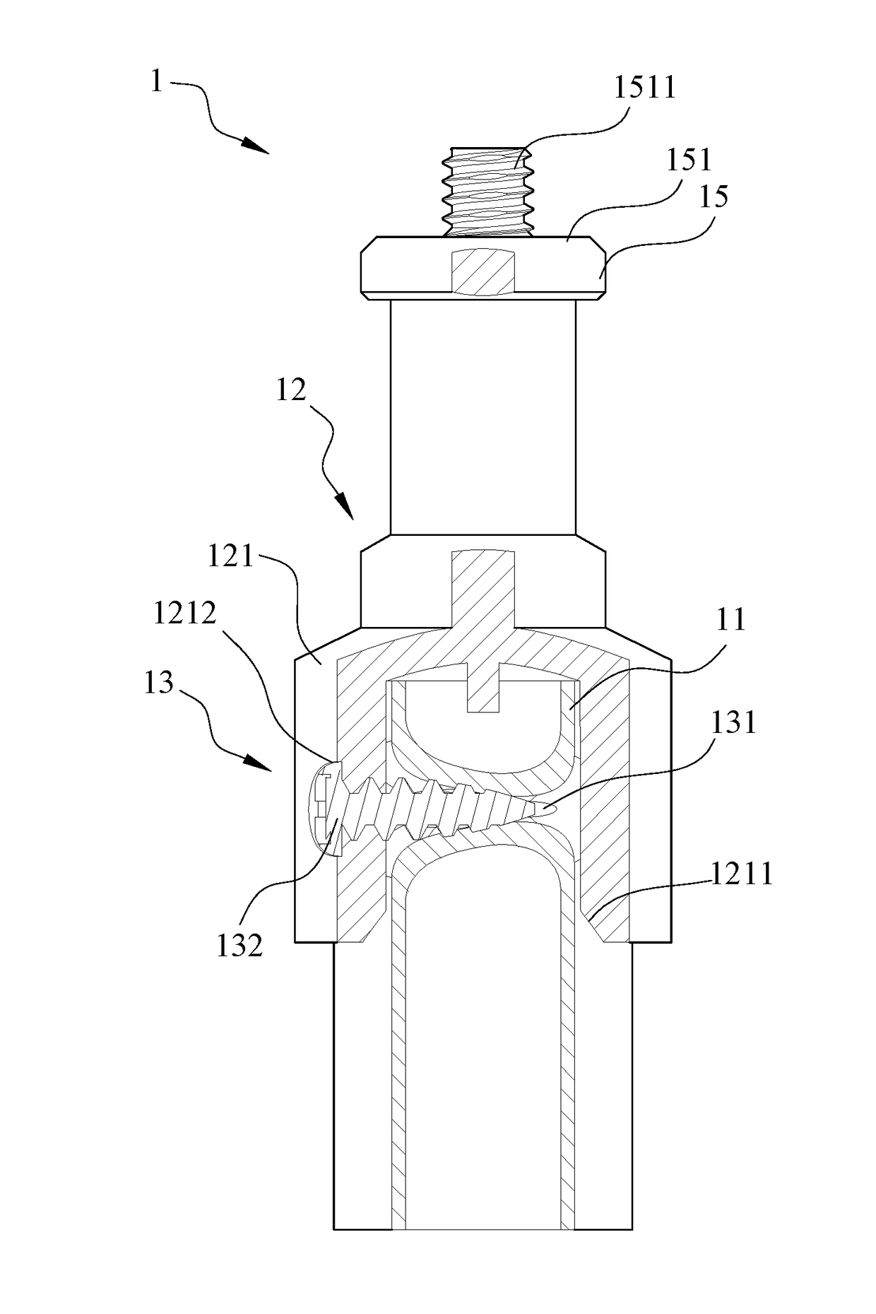
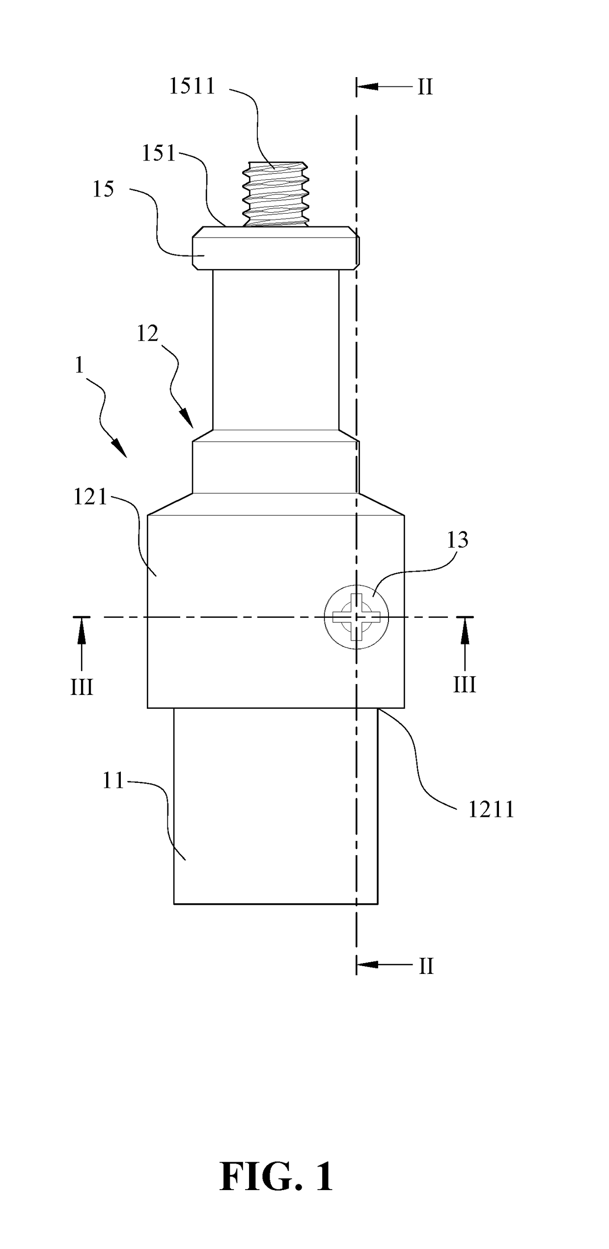
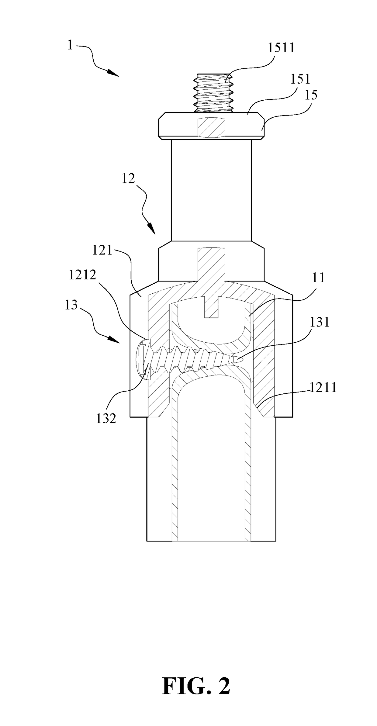
[0027]According to the present invention, the sleeve 12 further has a second coupling portion 15 with a narrowed width and located adjacent to the first coupling portion 121. Preferably, the second coupling portion 15 has a connection seat 151 and a coupler screw 1511 extending upwardly and axially from the connection seat 151 such that a camera carrier or a projection carrier can be mounted on the coupler screw 1511. By utilizing the side lock sleeve assembly 1 of the present invention, the sleeve 12 can be stably mounted on the first tube 11 at a preset position and hence is prevented from rotation or sliding relative to the first tube 11 even under the outside influence. Due to this advantages, the side lock sleeve assembly 1 of the present invention can be implemented in a camera tripod, which is another usage of the present invention.

[0028]Referring to FIG. 4, wherein FIG. 4 is an enlarged view of a first tube employed in the side lock sleeve assembly according to the first emb...

second embodiment

[0031]As shown in FIG. 7, a hole 1212 is formed on the first coupling portion 121 at a position between a center of the first receiving space 1211 and an outer surface of the sleeve 12. Note that the first tube 11 extends into the first receiving space 1211 while the fastening screw 13 has the extension section 131 extended threadedly through the hole 1212 in order to retain the extension section between the sleeve 12 and the first tube 11. The side lock sleeve assembly of the second embodiment can serve as one telescopic central tube in a tripod stand.

[0032]FIG. 8 is an enlarged view of first and second tubes employed in the side lock sleeve assembly according to the second embodiment of the present invention without the sleeve 12. Since the threaded fitting portion 14 is formed on the outer surface of the first tube 11 and the threaded fitting portion 14 complements with the extension section 131 of the fastening screw 13, a greater engagement contact area is formed among the fast...


PUM


Abstract

A side lock sleeve assembly includes: a first tube, a sleeve having a first coupling portion defining a first receiving space for sleeving over the first tube, wherein a hole is formed on the first coupling portion at a position between a center of the first receiving space and an outer surface of the sleeve; and a fastening screw having an operation section and an extension section, wherein a diameter of the screw gradually decreases from the operation section toward the extension section such that threadedly extension of the extension section through the hole to retain the extension section between the sleeve and the first tube and such that threadedly insertion of the extension section of the screw through the hole results in a threaded fitting portion on an outer surface of the first tube complementing with the extension section, thereby snugly receiving the extension section of the screw therein.

Description

BACKGROUND OF THE INVENTION1. Field of the Invention[0001]The present invention relates generally to a tube assembly, and more particularly to a side lock sleeve assembly for use in an equipment, such as tripod camera stand and the likes.2. The Prior Arts[0002]A conventional tube assembly generally includes a basic tube and a sleeve and a plurality of fixing means are used for fixing the sleeve relative to the basic tube. The most general fixing means is that a fastening screw is inserted through the sleeve and the basic tube for fixing the two relative to each other. Such type of fixing method is only suitable for the basic tube having a relative wall thickness and in case of the basic tube with thin wall thickness, after the fixing operation, wobbling may result between the sleeve and the basic tube.[0003]The tube assemblies employed in portable tables, chairs in camping campus and tripod camera stand tend toward light weight in general. Due to advance of technology, the wall conf...

Claims


Application Information

Patent Timeline
Patent Type & Authority Applications(United States)
IPC IPC(8): F16B7/14
CPCF16M11/34F16B7/1418F16B7/182F16B7/185F16M11/245F16M11/28F16M2200/025F16M2200/027Y10T403/32501Y10T403/4949Y10T403/7084F16B7/1472
Inventor LIN, CHIEN-TING
Owner LIN CHIEN TING
Why Eureka
Try Eureka