Electroluminescent display device

a technology display device, which is applied in the direction of semiconductor devices, instruments, electrical apparatus, etc., can solve the problem of reducing the driving property of electroluminescent display device, and achieve the effect of improving storage capacitan

Active Publication Date: 2018-06-28
LG DISPLAY CO LTD
View PDF8 Cites 15 Cited by
  • Summary
  • Abstract
  • Description
  • Claims
  • Application Information

AI Technical Summary

Problems solved by technology

However, in the related art electroluminescent display device, a threshold voltage of the driving TFT Td is fluctuated (or changed) such that there is a problem in providing a desired image display.
In addition, since there is a limitation of the storage capacitance, the driving property of the electroluminescent display device is decreased.

Method used


Image

  • Electroluminescent display device
  • Electroluminescent display device
  • Electroluminescent display device

Examples


first embodiment

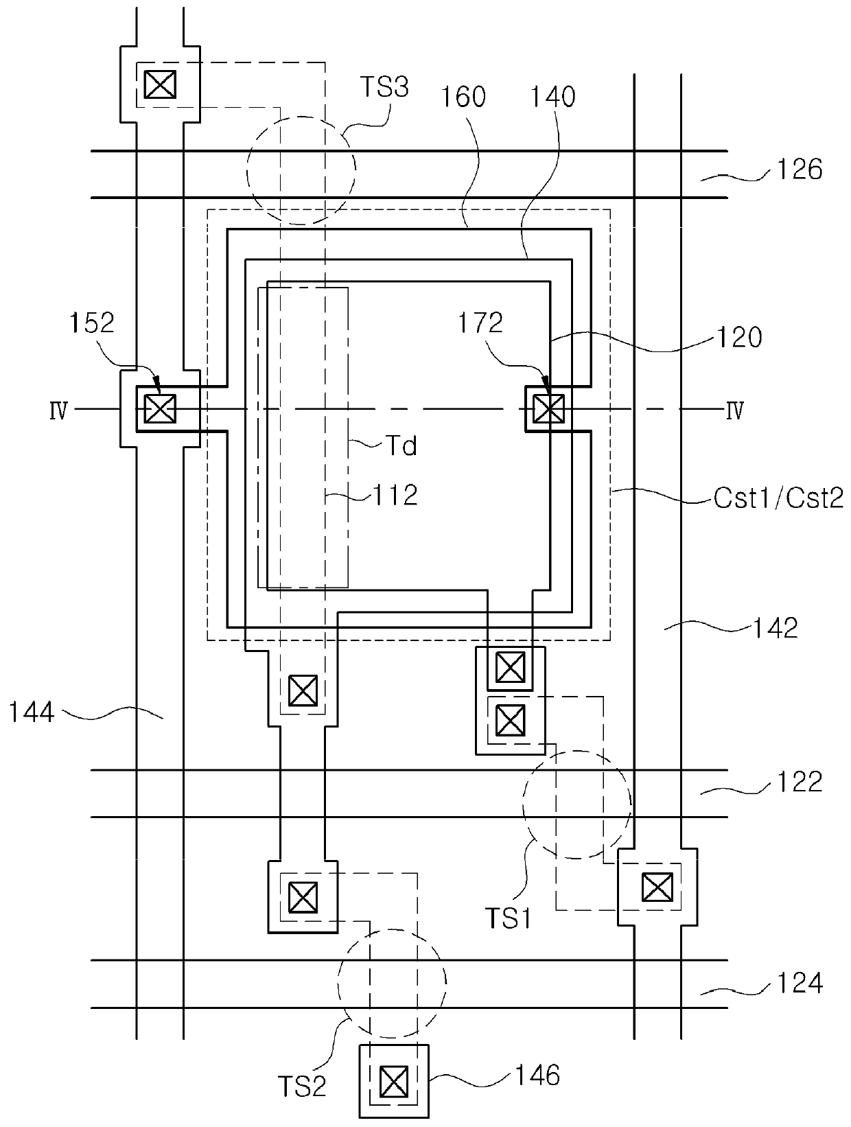
[0035]FIG. 3 is a schematic plane view of one pixel region of an electroluminescent display device according to the present invention, and FIG. 4 is a cross-sectional view taken along the line IV-IV of FIG. 3.

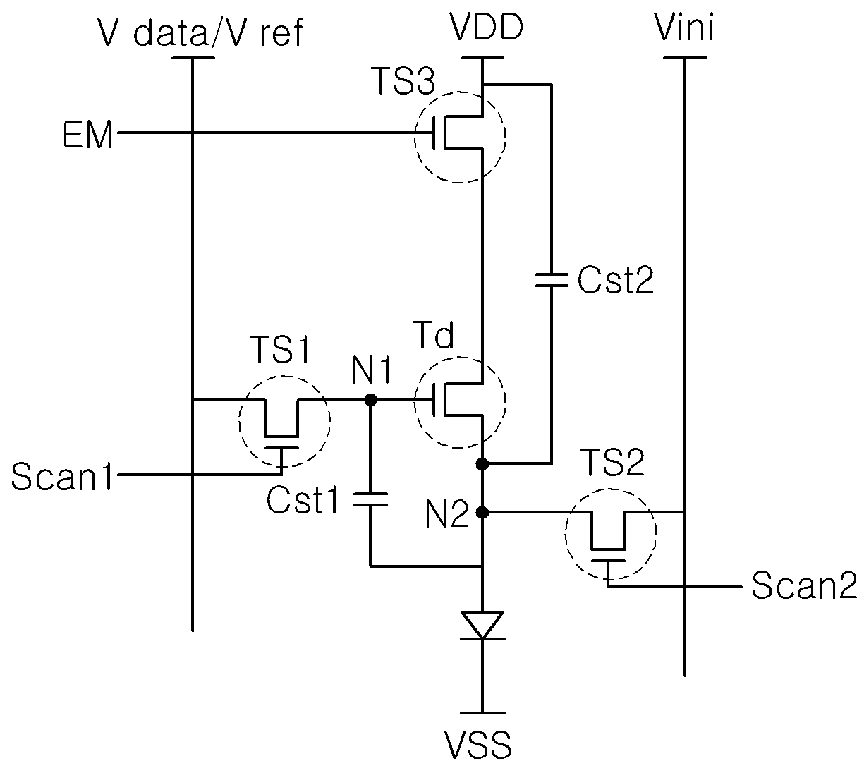
[0036]Referring to FIGS. 3 and 4, with reference to FIG. 2, an electroluminescent display device 100 according to a first embodiment of the present invention includes an emitting diode D, a driving TFT Td, first to third switching TFTS TS1, TS2 and TS3 and first and second capacitors Cst1 and Cst2.

[0037]In addition, the electroluminescent display device 100 includes first and second scan signal lines 122 and 124 along a first direction, an emitting signal line 126, a data line 142 along a second direction crossing the first direction, a power line 144 and an initial signal line 146. The first and second scan signal lines 122 and 124 and the emitting signal line 126 extend along a first direction, and the data line 142, the power line 144 and the initial signal line 146 extend a...

second embodiment

[0056]FIG. 5 is a schematic plane view of one pixel region of an electroluminescent display device according to the present invention.

[0057]Referring to FIG. 5, with respect to FIG. 2, an electroluminescent display device 200 according to a second embodiment of the present invention includes an emitting diode D, a driving TFT Td, first to third switching TFTS TS1, TS2 and TS3 and first and second capacitors Cst1 and Cst2.

[0058]In addition, the electroluminescent display device 200 includes first and second scan signal lines 222 and 224, an emitting signal line 226, a data line 262, a power line 264 and an initial signal line 266. The first and second scan signal lines 222 and 224 and the emitting signal line 226 extend along a first direction, and the data line 262, the power line 264 and the initial signal line 266 extend along a second direction crossing the first direction.

[0059]The first switching TFT TS1 is connected to the first scan signal line 222 and the data line 262, and ...


PUM


Abstract

A display device includes a driving thin film transistor (TFT) having a two-gate overlap structure and a power line having a width extension structure that together allow for improved storage capacitance when compared to a display device without such structures.

Description

[0001]The present application claims the benefit of Korean Patent Application No. 10-2016-0181411 filed in Korea on Dec. 28, 2016, which is hereby incorporated by reference.BACKGROUNDTechnical Field[0002]The present disclosure relates to an electroluminescent display device and more particularly to an electroluminescent display device having an improved storage capacitance.Discussion of the Related Art[0003]Among flat panel display devices, since an electroluminescent display device is a self-emission type, the electroluminescent display device has excellent characteristics of a wide viewing angle, a high contrast ratio in comparison to a liquid crystal display device and also the electroluminescent display device has characteristics of a thin profile and low power consumption because the electroluminescent display device does not need a back-light unit.[0004]In addition, the electroluminescent display device can be driven by a direct low voltage and has advantages in a response tim...

Claims


Application Information

Patent Timeline
Patent Type & Authority Applications(United States)
IPC IPC(8): G09G3/3266G09G3/3225H01L27/32
CPCG09G3/3266G09G3/3225H01L27/3262H01L27/3265H01L27/3276G09G3/3233H01L27/1255G09G2300/0819G09G2300/0852G09G2300/0861G09G2300/0876G09G2310/0251G09G2310/0262H10K59/1216H10K10/482H01L27/124H10K59/123H10K59/124H10K59/1213H10K59/131
Inventor YOO, JUHN-SUKKWON, WOO-HYUN
Owner LG DISPLAY CO LTD
Why Eureka
Try Eureka