Electrical connector assembly

US20180212366A1Active Publication Date: 2018-07-26LOTES
10 Cites 3 Cited by

Patent Information

Authority / Receiving Office
US · United States
Current Assignee / Owner
Publication Date
2018-07-26

Smart Images

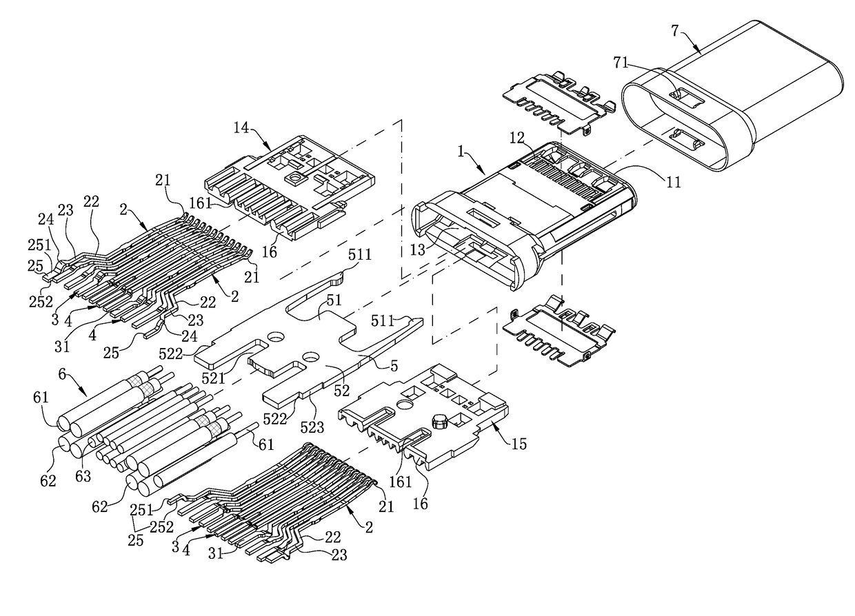
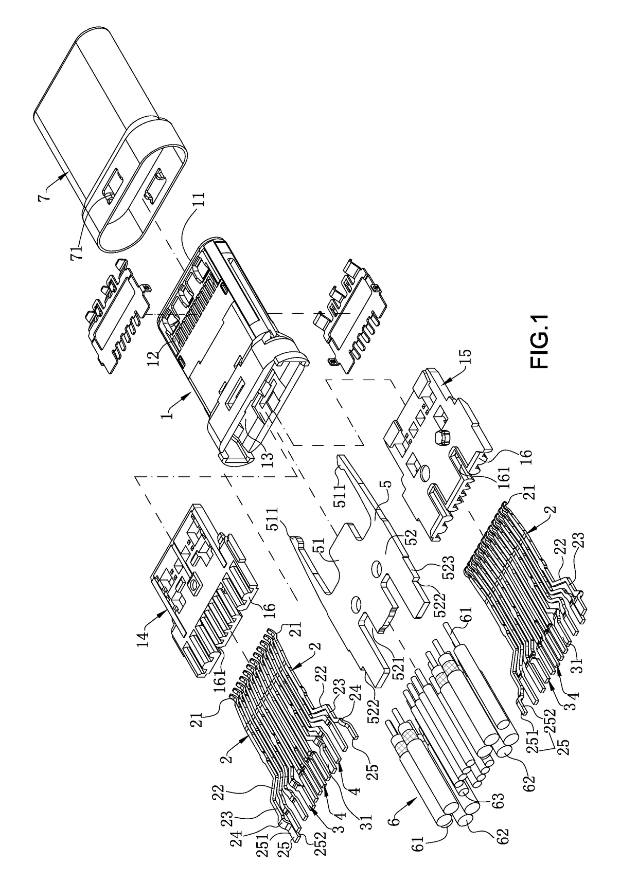
  • Figure 1
    Figure 1
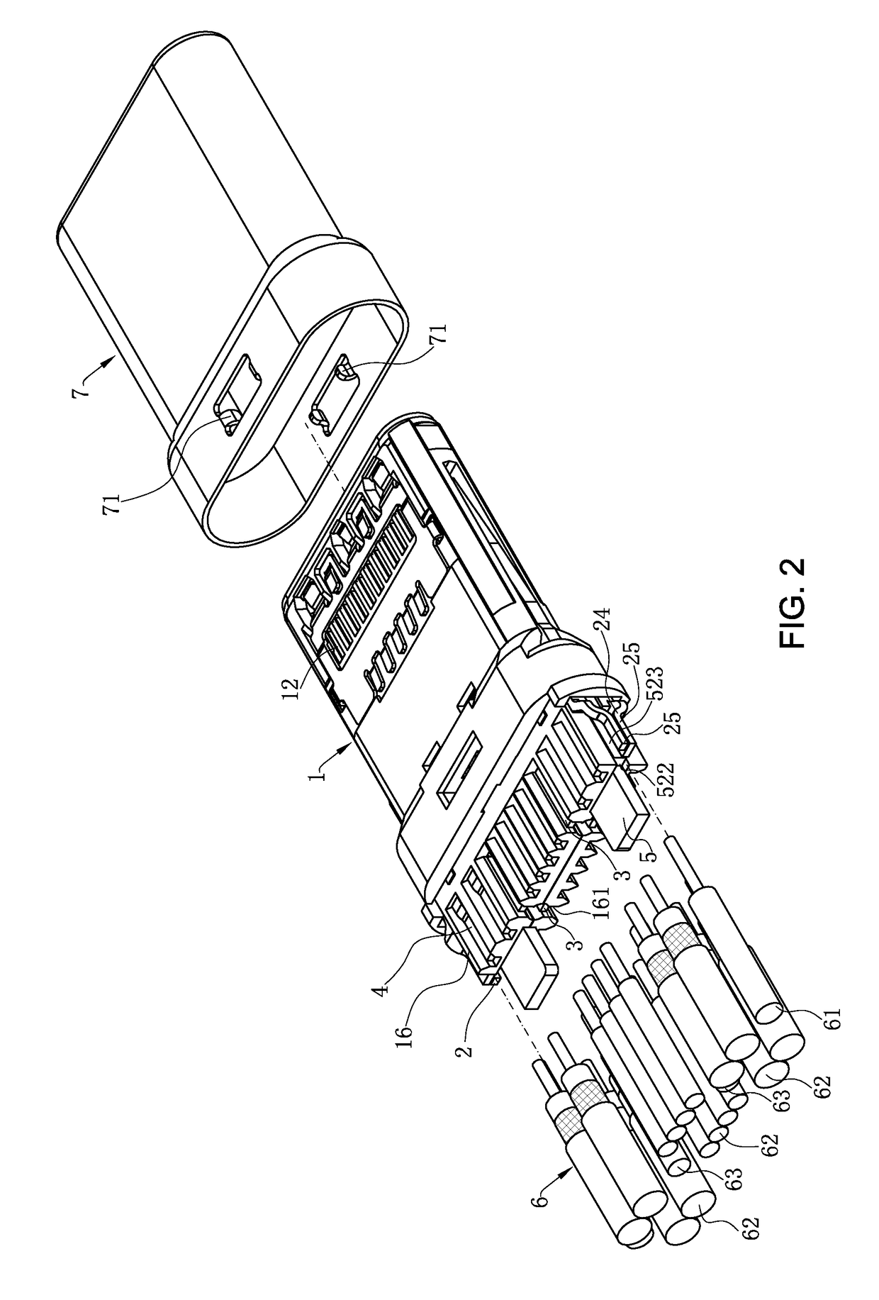
  • Figure 2
    Figure 2
  • Figure 3
    Figure 3
Patent Text Reader

Abstract

An electrical connector assembly includes an insulating body, multiple signal terminals received in the insulating body, a metal ground member fixed on the insulating body, and at least one ground core wires. The metal ground member has a plate surface and a cutting surface connected with the plate surface. The ground core wire is soldered to the cutting surface. The cutting surface is rough, the frictional force between the cutting surface and the ground core wires is great.
Need to check novelty before this filing date? Find Prior Art

Description

CROSS-REFERENCE TO RELATED APPLICATION

[0001] This non-provisional application claims priority to and benefit of, under 35 U.S.C. § 119(a), Patent Application No. 201720093901.9 filed in P.R. China on Jan. 24, 2017, the entire content of which is hereby incorporated by reference.FIELD OF THE INVENTION

[0002] The present invention relates to an electrical connector assembly, and more particularly to an electrical connector assembly in which terminals are directly soldered to a cable.BACKGROUND OF THE INVENTION

[0003] An existing electrical connector assembly includes an insulating body, multiple signal terminals arranged in the insulating body, a metal ground member fixed in the insulating body, and a cable having multiple signal core wires and multiple ground core wires. The signal core wires are soldered correspondingly to the plate surfaces of the signal terminals, and the ground core wires are soldered correspondingly to the plate surfaces of the ground member. However, because the pla...

Examples

Embodiment Construction

[0040]The present invention is more particularly described in the following examples that are intended as illustrative only since numerous modifications and variations therein will be apparent to those skilled in the art. Various embodiments of the invention are now described in detail. Referring to the drawings, like numbers indicate like components throughout the views. As used in the description herein and throughout the claims that follow, the meaning of “a”, “an”, and “the” includes plural reference unless the context clearly dictates otherwise. Also, as used in the description herein and throughout the claims that follow, the meaning of “in” includes “in” and “on” unless the context clearly dictates otherwise. Moreover, titles or subtitles may be used in the specification for the convenience of a reader, which shall have no influence on the scope of the present invention.

[0041]It will be understood that when an element is referred to as being “on” another element, it can be di...