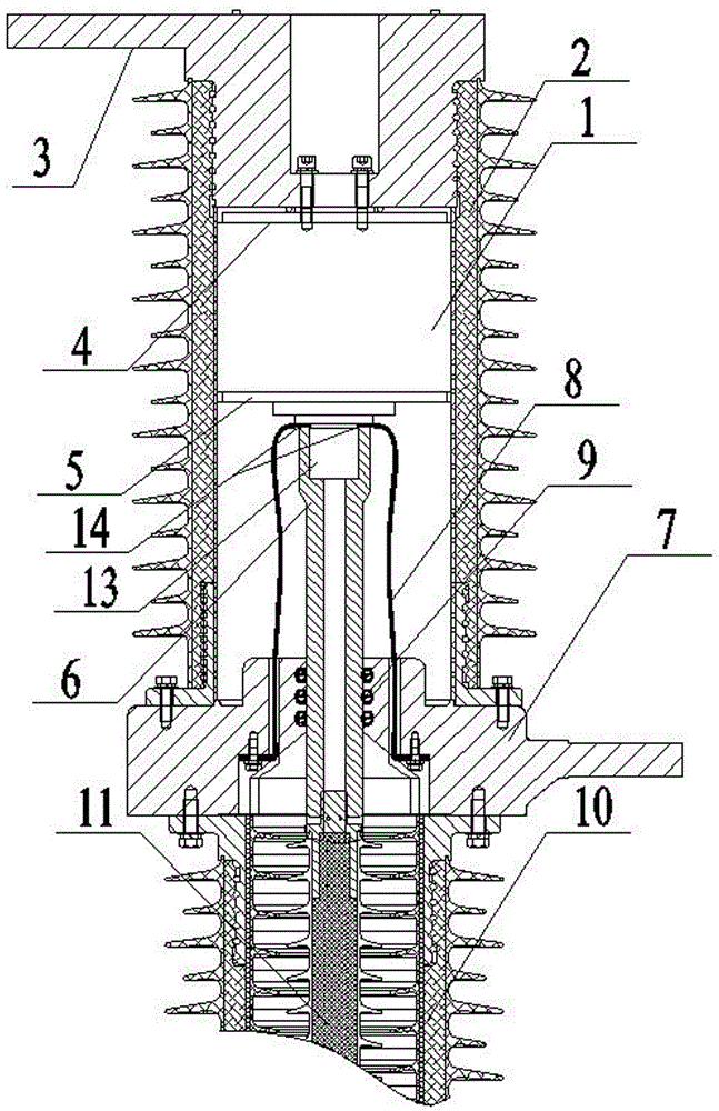
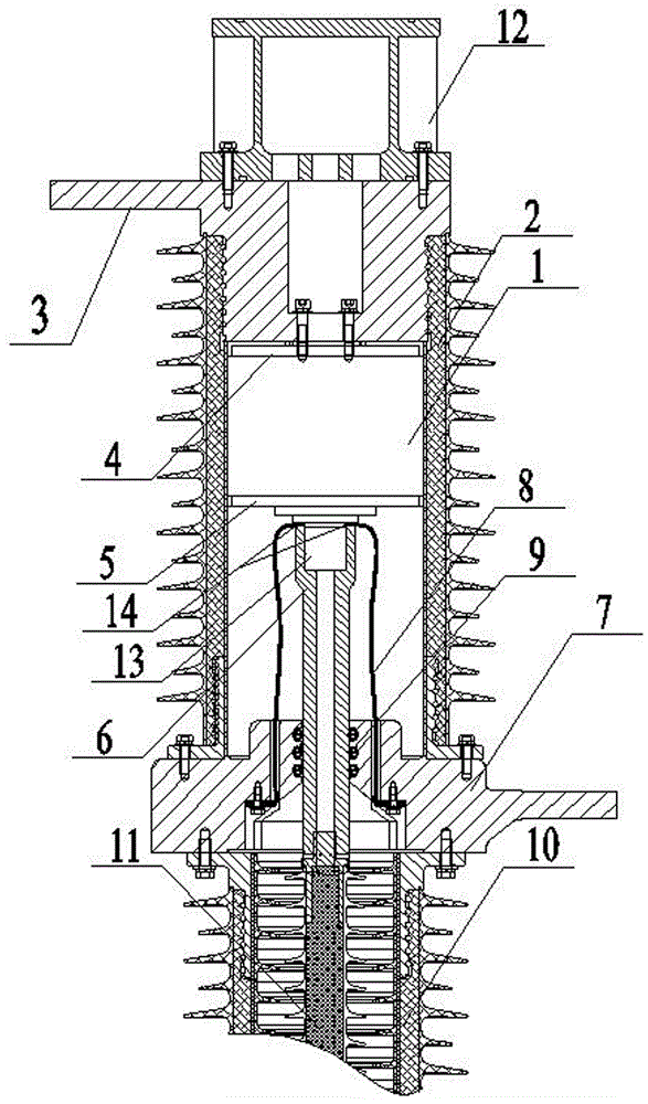
A high voltage vacuum circuit breaker pole
A technology for vacuum circuit breakers and poles, which is applied to high-voltage air circuit breakers, high-voltage/high-current switches, circuits, etc., can solve the problems of reducing the service life of circuit breakers, the trend of temperature rise is not obvious, and the insulation structure is damaged. High heat dissipation efficiency, elimination of local hot spots, uniform heat distribution
- Summary
- Abstract
- Description
- Claims
- Application Information
AI Technical Summary
Problems solved by technology
Method used
Image
Examples
Embodiment 1
[0023] A pole of a high-voltage vacuum circuit breaker according to the present invention, such as figure 1 and 3As shown, it includes an upper outlet seat 3 , a vacuum interrupter 1 , a moving conductive rod 6 , a lower outlet seat 7 and a finger spring 9 . The upper end of the vacuum interrupter 1 is connected to the upper outlet seat 3, and the lower end is connected to the lower outlet seat 7. The interior of the vacuum interrupter 1 is provided with a static end 4 and a movable end 5, and the static end 4 and the movable end 5 are arranged correspondingly. , and the static end 4 is located above the moving end 5, the static end 4 is connected to the upper outlet seat 3, the lower part of the moving end 5 is connected to the moving conductive rod 6, and the moving conductive rod 6 is arranged between the vacuum interrupter 1 and the lower outlet seat 7 between, and the upper part of the moving conductive rod 6 is connected to the lower part of the moving end 5, and the lo...
Embodiment 2
[0026] A pole of a high-voltage vacuum circuit breaker according to the present invention, such as figure 2 and 3 As shown, it includes an upper outlet seat 3 , a vacuum interrupter 1 , a moving conductive rod 6 , a lower outlet seat 7 and a finger spring 9 . The upper end of the vacuum interrupter 1 is connected to the upper outlet seat 3, and the lower end is connected to the lower outlet seat 7. The interior of the vacuum interrupter 1 is provided with a static end 4 and a movable end 5, and the static end 4 and the movable end 5 are arranged correspondingly. And the static end 4 is located above the moving end 5, the static end 4 is connected to the upper outlet seat 3, the lower part of the moving end 5 is connected to the moving conductive rod 6, and the moving conductive rod 6 is arranged between the vacuum interrupter 1 and the lower outlet seat 7 , the upper part of the moving conductive rod 6 is connected to the lower part of the moving end 5, and the lower part of...
PUM
 Abstract
Description
Claims
Application Information
 - R&D
- Intellectual Property
- Life Sciences
- Materials
- Tech Scout
- Unparalleled Data Quality
- Higher Quality Content
- 60% Fewer Hallucinations
Browse by: Latest US Patents, China's latest patents, Technical Efficacy Thesaurus, Application Domain, Technology Topic, Popular Technical Reports.
© 2025 PatSnap. All rights reserved.Legal|Privacy policy|Modern Slavery Act Transparency Statement|Sitemap|About US| Contact US: help@patsnap.com


