Light source device and projection type display apparatus

a technology of projection type and display apparatus, which is applied in the direction of projectors, optics, instruments, etc., can solve the problems of image display apparatus problems, material deterioration, efficient light-emitting,

Active Publication Date: 2018-11-01
LIGHT SHOW TECH CO LTD
View PDF4 Cites 11 Cited by
  • Summary
  • Abstract
  • Description
  • Claims
  • Application Information

AI Technical Summary

Problems solved by technology

However, when the same point on the phosphor always continues to be illuminated with the excitation light, there is a case where temperature increases and light-emitting efficiently decreases, or there is a likelihood that material deterioration will occur.
For this reason, the ununiformity occurs to the fluorescence that is reflected by the dichroic mirror 5, and color irregularity or reduction in a light amount occurs that causes a problem to an image display apparatus.
Besides the example described abo...

Method used


Image

  • Light source device and projection type display apparatus
  • Light source device and projection type display apparatus
  • Light source device and projection type display apparatus

Examples


first embodiment

[0039]A projection type display apparatus that includes a light source device according to a first embodiment of the present invention will be described with reference to FIG. 1. The light source device will be first described and then the entire projection type display apparatus will be described.

Light Source Device

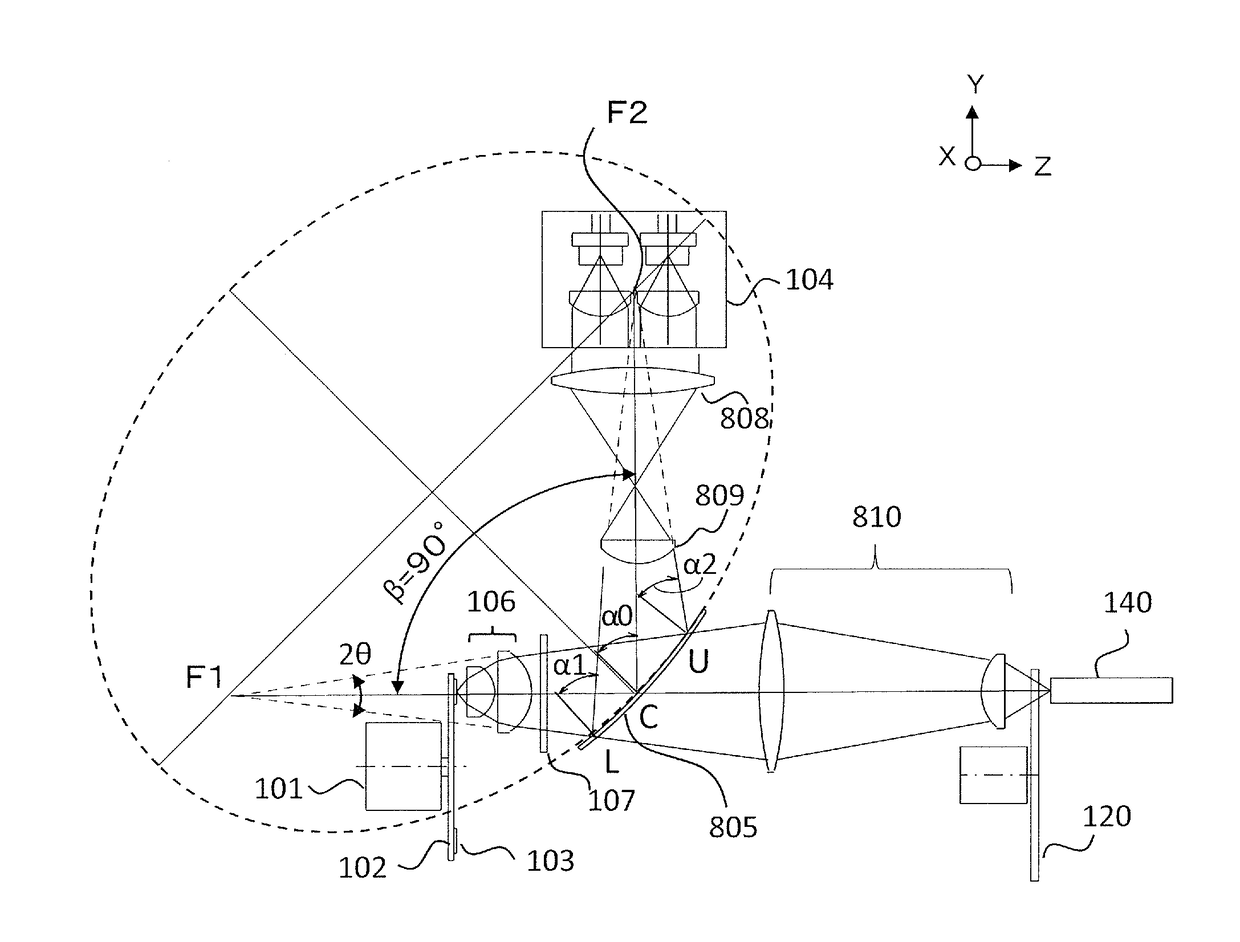
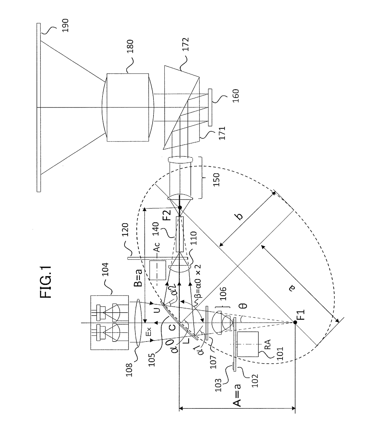
[0040]In FIGS. 1, 101, 102, 103, 104, 105, 106, 107, and 108 depict a motor, a rotator, a phosphor, an excitation light source unit, a surface-curved dichroic mirror, a converging lens, a ¼-wavelength plate, and an excitation light source-side lens, respectively.

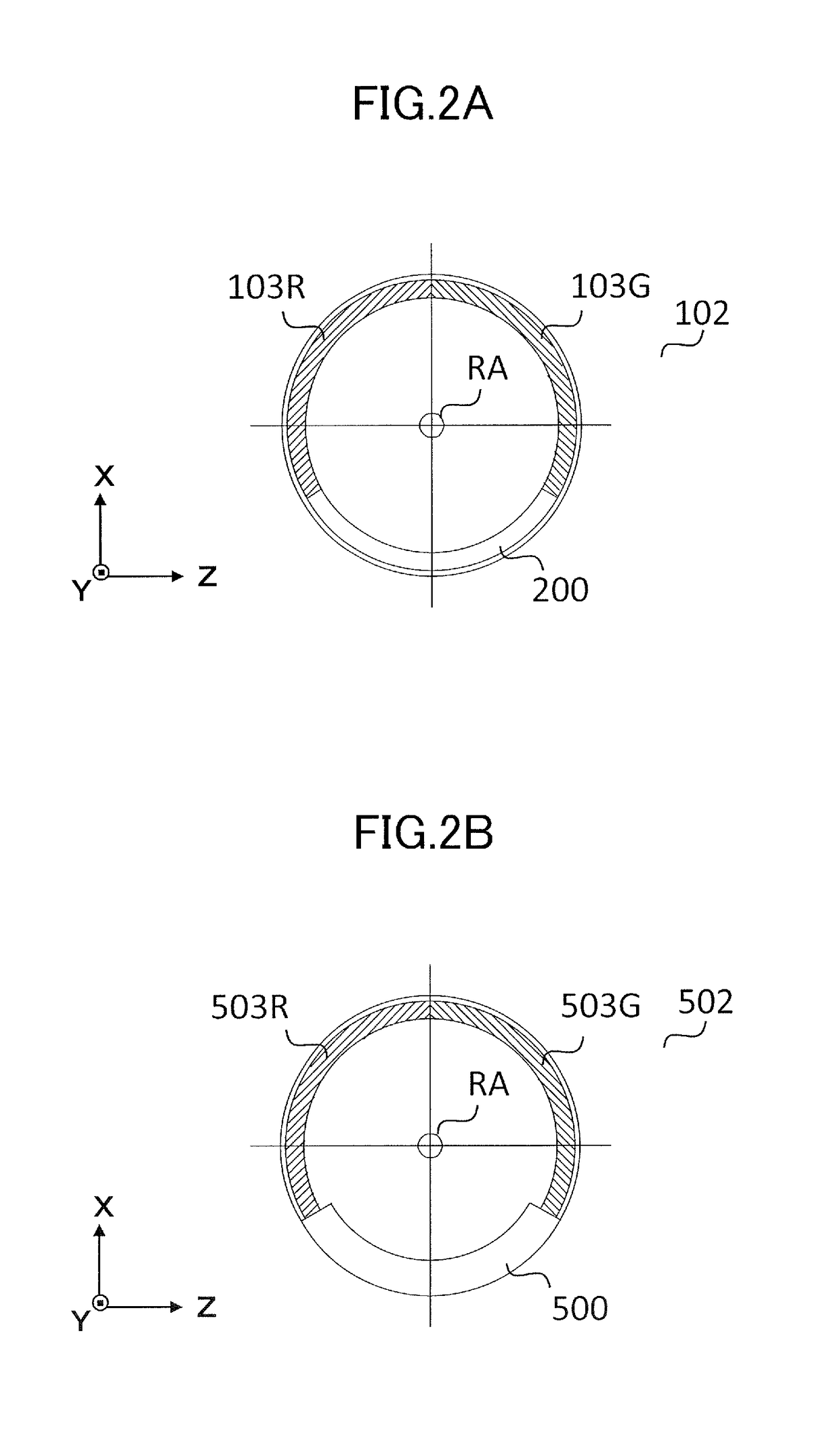
[0041]In the apparatus, the phosphor 103 is provided on a principal surface of the rotator 102 that is rotatable by the motor 101. FIG. 2A is a plan-view diagram illustrating the rotator 102, when viewed from the converging lens 106 side. On the principal surface of the rotator 102, a red phosphor 103R and a green phosphor 103G that have different light emission wavelength characteristics are caused to cover a po...

second embodiment

[0079]In the first embodiment, with regard to the blue light for image display, the excitation light is caused to be reflected on the reflection portion 200 of the rotator 102, is converted into the S polarization light through the ¼-wavelength plate 107, and is caused to be reflected on the concave surface of the surface-curved dichroic mirror 105. In contrast, in a second embodiment, a transmission portion that causes the excitation light to pass through a portion of the rotator is provided without performing polarization conversion of the blue light for image display using the ¼-wavelength plate. The blue light that passes through is led to the convex surface side of the surface-curved dichroic mirror through the mirror and the converging lens, is caused to pass through the surface-curved dichroic mirror, and is caused to be incident on a projection optical system of the projection type display apparatus.

[0080]A light source device and a projection type display apparatus accordin...

third embodiment

[0086]A third embodiment is illustrated as a modification example of the first embodiment in FIG. 6. In the same manner as the first embodiment, the third embodiment also includes the motor 101, the rotator 102, the phosphor 103, the excitation light source unit 104, the converging lens 106, the ¼-wavelength plate 107, the excitation light source-side lens 108, the relay lens 110, the color selection wheel 120, and the light tunnel 140. Furthermore, in the same manner, the illumination lens 150, the light modulation device 160, the prism 171, the prism 172, the projection lens 180, and the projection screen 190 that are illustrated in FIG. 1, are also included although illustrations thereof are omitted in FIG. 6. These individual constituent elements, unless particularly described, are assumed to have the same configurations as in the first embodiment.

[0087]Also in the third embodiment, the numerical aperture (NA) of the converging lens 106 is 0.174. Because NA=sin θ, the converging...


PUM


Abstract

A light source device for a projection type display apparatus includes a phosphor, an excitation light source, a surface-curved dichroic minor, and a converging lens. The excitation light source configured to output excitation light for exciting the phosphor. The surface-curved dichroic minor has a curved surface and configured to cause one of excitation light from the excitation light source and fluorescence from the phosphor to pass through the curved surface and to cause the other to be reflected on the curved surface. The surface-curved dichroic mirror causes the light that passes through, neither to substantially converge, nor to substantially diverge, but performs a converging operation on the light that is reflected.

Description

BACKGROUND OF THE INVENTIONField of the Invention[0001]The present invention relates to a light source device that includes a semiconductor laser, a phosphor, and a dichroic mirror, and a projection type display apparatus that uses the light source device.Description of the Related Art[0002]In recent years, semiconductor lasers have been developed that output light with a short wavelength with high light-emitting efficiency. A phosphor is excited by output light of the semiconductor laser, and light that is wavelength-converted by the phosphor is used as a light source for a projection type display apparatus.[0003]The phosphor may be held at a fixed place and may be illuminated with excitation light. However, when the same point on the phosphor always continues to be illuminated with the excitation light, there is a case where temperature increases and light-emitting efficiently decreases, or there is a likelihood that material deterioration will occur. For this reason, the phosphor...

Claims


Application Information

Patent Timeline
IPC IPC(8): G03B21/20
CPCG03B21/208G03B21/204G03B21/2066G02B27/1006G03B21/20G03B33/08
Inventor YAMAKAGE, AKIHIROMEI, YUFEI
Owner LIGHT SHOW TECH CO LTD
Why Eureka
Try Eureka