Planar light source and illumination apparatus

Active Publication Date: 2019-02-14
KANEKA CORP
View PDF10 Cites 1 Cited by
  • Summary
  • Abstract
  • Description
  • Claims
  • Application Information

AI Technical Summary

Benefits of technology

The patent text aims to provide a technical solution to a problem that was previously present. It describes the issue that was causing difficulties and how the proposed solution aims to overcome it. This solution can be implemented in a specific field or for a specific purpose.

Problems solved by technology

Therefore, high design property is required.

Method used


Image

  • Planar light source and illumination apparatus
  • Planar light source and illumination apparatus
  • Planar light source and illumination apparatus

Examples


first embodiment

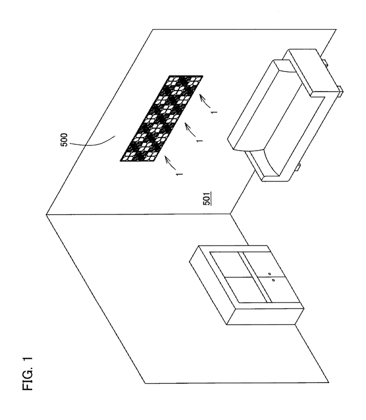
[0069]As illustrated in FIG. 1, an illumination apparatus 1 according to the present invention is mounted to a mounting surface 500 which is a surface of a wall, a ceiling, a floor, or the like, and illuminates a living space 501 side. The illumination apparatus 1 is arranged side by side with other plural illumination apparatuses 1 to constitute one illumination system.

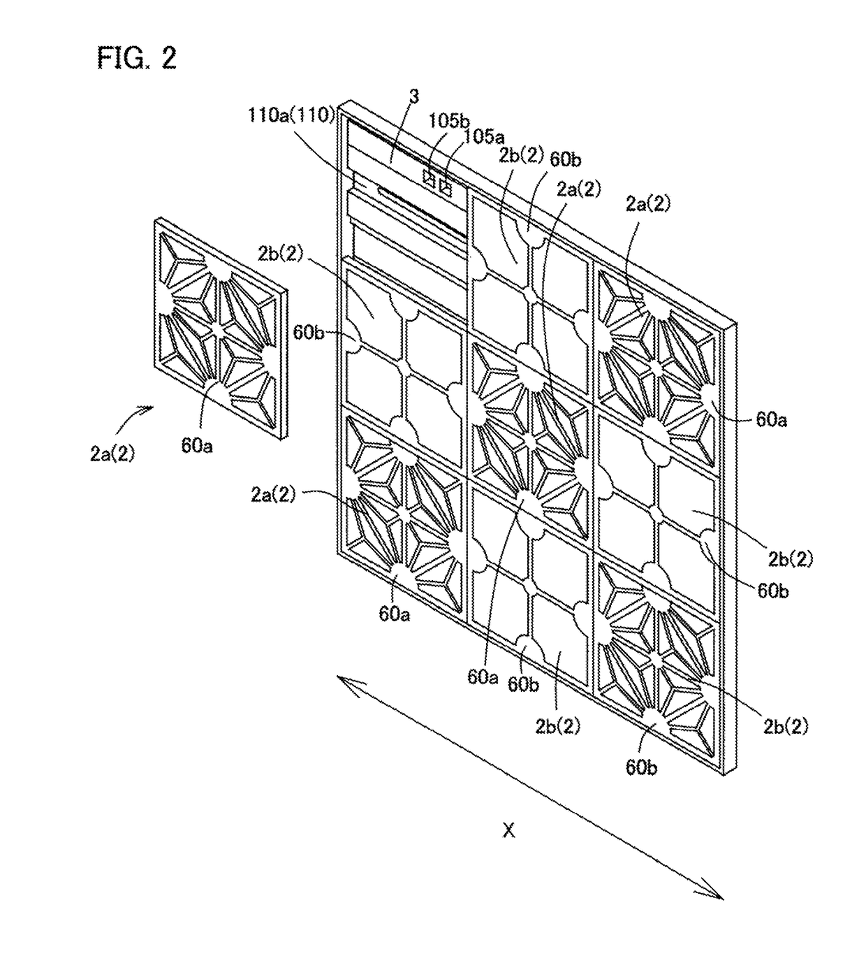
[0070]As illustrated in FIG. 2, the illumination apparatus 1 includes one or more types of planar light sources 2 and a mounting member 3.

[0071]Here, in the following description, in order to facilitate understanding, a case will be described where the illumination apparatus 1 is configured by combining two types of planar light sources 2 (2a, 2b) including pattern forming sections 60 (60a, 60b) having different shapes.

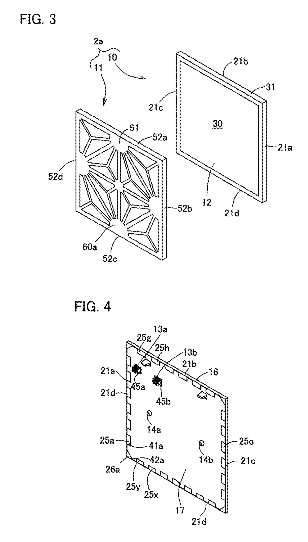
[0072]As illustrated in FIG. 3, the planar light source 2a includes a planar light emitting panel 10 and a decorative member 11.

[0073]The planar light emitting panel 10 is a light emitting panel which ...

second embodiment

[0204]According to the illumination apparatus 200 of the second embodiment, since the posture of the planar light source 2 with respect to the mounting surface 500 can be changed, there are few restrictions on the installation place.

[0205]According to the illumination apparatus 200 of the second embodiment, the fastening element 505 is hardly disengaged since the removal direction of the fastening element 505 is blocked by the end surface of the light emitting panel when the planar light source 2 is installed in the horizontal posture.

[0206]According to the illumination apparatus 200 of the second embodiment, since the fall prevention member 216 is provided, it is possible to prevent the planar light source 2 from dropping onto the ground even if the planar light source 2 is detached from the mounting member 203.

[0207]Subsequently, a planar light source 250 according to a third embodiment will be described. Note that identical reference numerals are given to configurations identical...

third embodiment

[0237]Similarly to the light-emission shielding section 253 of the third embodiment, as illustrated in FIG. 25A, a light-emission shielding section 301 of the planar light source 300 is divided into four first regions 302a, 302b, 265c, 302d by a lateral shielding section 255 and a longitudinal shielding section 256.

[0238]Each of the first regions 302a, 302b, 302d is a rectangular region, and specifically has a square shape.

[0239]The first region 302a is in line symmetry with the first region 302d with the lateral shielding section 255 as the axis of symmetry, and is in line symmetry with the first region 302b with the longitudinal shielding section 256 as the axis of symmetry.

[0240]As can be seen from FIG. 25B, the first region 302a (302b, 302d) is divided into five divided regions 307a to 307e by a second connecting shielding section 303 and second branch shielding sections 305, 306.

[0241]The second connecting shielding section 303 is a section that crosses the first region 302a (3...


PUM


Abstract

The present invention provides a planar light source and an illumination apparatus which have higher design property than that of conventional ones. The planar light source includes: a planar light emitting panel which has a light emitting surface; and a decorative member which covers the light emitting surface of the planar light emitting panel. A light emitting region which emits light when the planar light source is turned on and a non-light-emitting frame region which surrounds the light emitting region are provided on the light emitting surface. The decorative member has a pattern forming section. The pattern forming section includes a frame shielding section which covers entirety of the frame region in the front view, and a light-emission shielding section which extends from the frame shielding section so as to divide the light emitting region into a plurality of regions.

Description

TECHNICAL FIELD[0001]The present invention relates to a planar light source and an illumination apparatus that emit light in a planar shape.BACKGROUND ART[0002]Conventionally, an organic EL panel has been used as a light source of an illumination apparatus (for example, Patent Document 1). Since the organic EL panel is a planar light source and has characteristics of being thin and lightweight, there are few restrictions on the installation place of the organic EL panel. Therefore, in recent years, application of the organic EL panel for a wall-surface illumination apparatus as well as for a ceiling illumination apparatus is considered. The wall-surface illumination apparatus is installed on a surface of a wall or the like. The ceiling illumination apparatus is installed on a ceiling.[0003]The wall-surface illumination apparatus used for a surface of a wall or the like not only functions as illumination but also is used as part of an interior decoration. Therefore, high design prope...

Claims


Application Information

Patent Timeline
IPC IPC(8): F21S2/00F21V11/08F21V21/096
CPCF21V21/096F21S2/005F21Y2105/00F21W2121/00F21V11/08F21S8/032F21S8/033F21S8/04F21V11/00F21V15/01F21Y2115/20H10K50/10H10K50/00F21Y2115/15
Inventor TANAKA, MICHIRUNAKABAYASHI, AKANEJONOO, NAOKOFUJISAWA, KO
Owner KANEKA CORP
Why Eureka
Try Eureka