Radiolucent trial

Active Publication Date: 2019-10-03
WARSAW ORTHOPEDIC INC
View PDF13 Cites 1 Cited by
  • Summary
  • Abstract
  • Description
  • Claims
  • Application Information

AI Technical Summary

Problems solved by technology

However, visualization of the disc space in which the spinal fusion interbody is to be implanted is limited during surgery.
Nevertheless, because fluoroscopic images are typically only taken from lateral a

Method used


Image

  • Radiolucent trial
  • Radiolucent trial
  • Radiolucent trial

Examples


Example

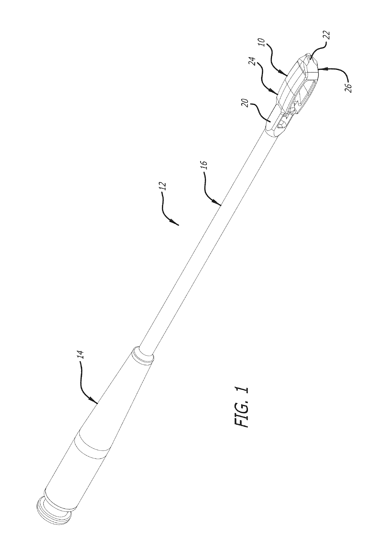
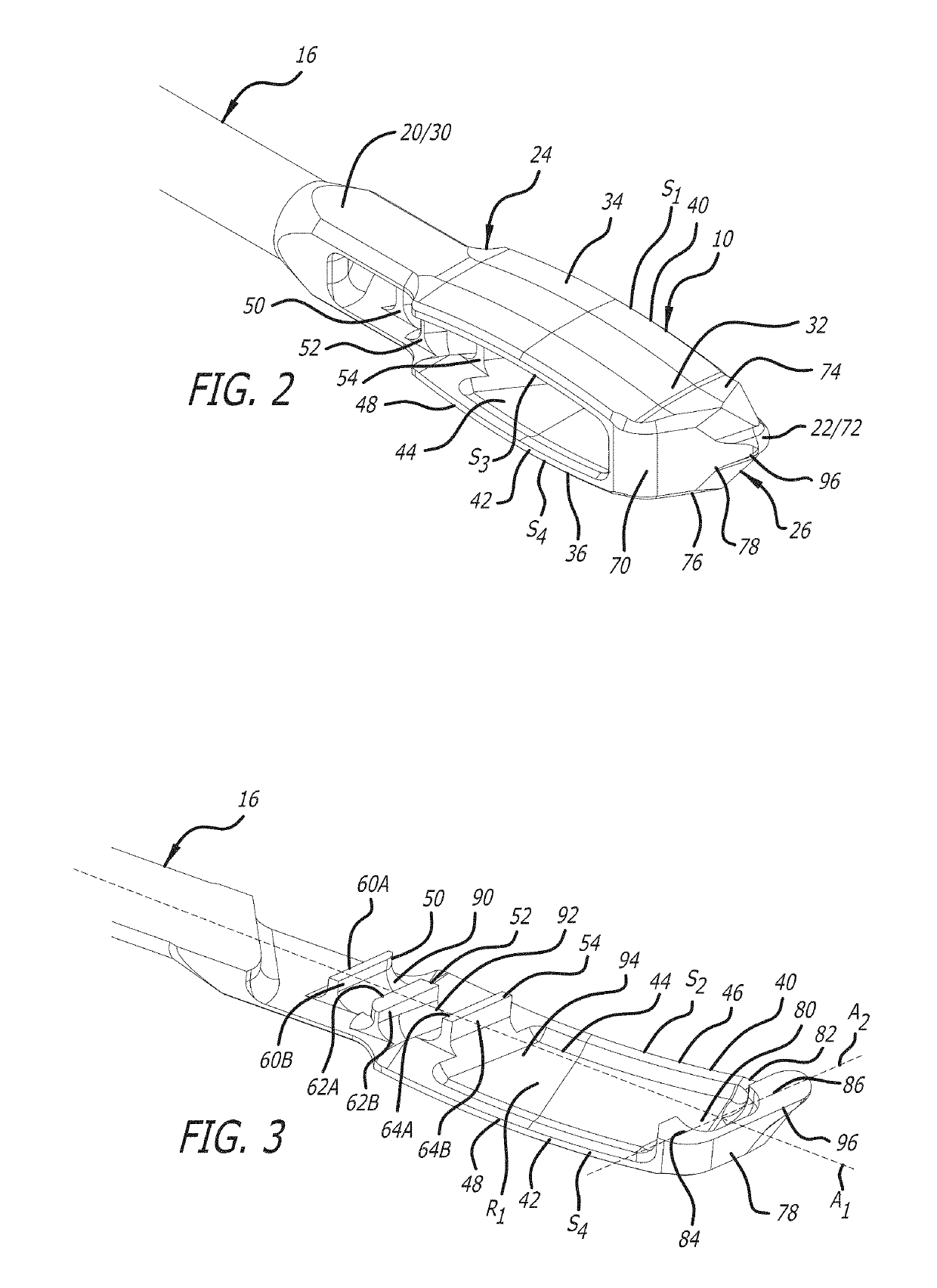
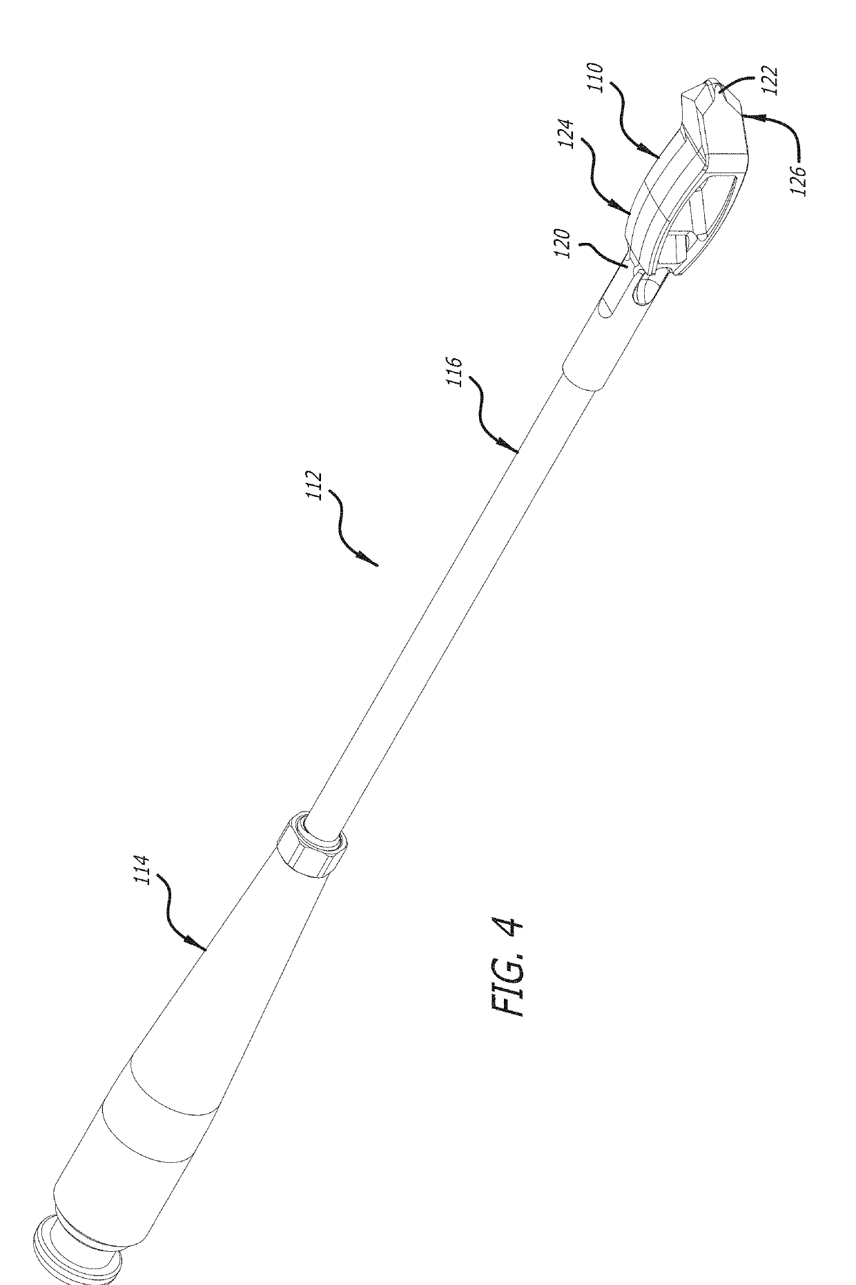
[0027]A spinal implant trial according to one embodiment of the present invention is generally referenced by the numeral 10 in FIGS. 1-3, and a spinal implant trial according to another embodiment of the present invention is generally referenced by the number 110 in FIGS. 4-21. The spinal implant trials 10 and 110 can be formed of materials such as carbon steel, stainless steel, titanium, cobalt chrome, PEEK, tantalum, or any combination of these. The spinal implant trials 10 and 110 can have various sizes corresponding to spinal implants having similar configurations and sizes. As such, a surgeon during surgery can insert various configurations and sizes of the spinal implant trials into a disc space between two adjacent vertebral bodies of a patient to enable the selection of a spinal implant configured and sized to fit the patient's disc space. As discussed below, the spinal implant trials 10 and 110 can also include features that afford selection of appropriately-sized spinal im...


PUM


Abstract

Spinal implant trials are provided having various configurations and sizes that aid the selection of spinal implants having similar configurations and sizes. A surgeon during surgery can insert various configurations and sizes of the spinal implant trials into a disc space between two adjacent vertebral bodies of a patient to enable the selection of a spinal implant configured and sized to fit the patient's disc space. Fluoroscopic images can be used in aiding the selection of an appropriately configured and sized spinal implant corresponding to one of the spinal implant trials. The spinal implant trials include features that reveal on the fluoroscopic images whether the spinal implant trials are properly oriented and positioned in the disc space. As such, the selection of the configuration and size of the spinal implants can be made after it is determined that the spinal implant trials are properly oriented and positioned within the disc space.

Description

FIELD OF THE INVENTION[0001]The present invention generally relates to a spinal implant trial. More particularly, the present invention relates to a spinal implant trial used to facilitate the selection of appropriately sized interbody spinal fusion implants. More particularly, the present invention relates to a spinal implant trial including features that reveal on fluoroscopic images whether the spinal implant trial is properly oriented and / or positioned in the disc space.DESCRIPTION OF THE PRIOR ART[0002]Widespread use of interbody spinal fusion implants has been adopted to treat disease of and injuries to the spine. Typically, spinal implant trials are used during surgery to select an appropriately configured and sized spinal fusion implant. Such spinal implant trials correspond to the shapes and dimensions of the spinal fusions available for use. For example, differently shaped and dimensioned spinal implant trials can be sequentially inserted into the disc space during surgery...

Claims


Application Information

Patent Timeline
IPC IPC(8): A61F2/46A61F2/44A61B6/12A61B6/00
CPCA61F2002/4475A61B6/487A61F2002/30168A61F2/447A61F2/4611A61F2002/3008A61F2/4684A61B6/12A61F2002/30271A61F2002/30056A61F2/4603A61F2002/30784A61F2/4465A61B8/0841A61F2002/30785A61F2002/30133A61F2002/30593A61F2002/30261
Inventor DEWEY, JONATHAN M.ARMSTRONG, WILLIAM D.MELKENT, ANTHONY J.
Owner WARSAW ORTHOPEDIC INC
Why Eureka
Try Eureka