Power line communication device, in-vehicle device and in-vehicle system

a technology of in-vehicle device and communication device, which is applied in the direction of transmission/receiving by adding signal to wave, power distribution line transmission, transportation and packaging, etc., can solve the problems of increasing manufacturing cost of automobiles and fuel consumption deterioration, so as to reduce loss, reduce component costs, and reduce loss.

Active Publication Date: 2020-09-24
HITACHI ASTEMO LTD
View PDF0 Cites 9 Cited by
  • Summary
  • Abstract
  • Description
  • Claims
  • Application Information

AI Technical Summary

Benefits of technology

[0011]The effects obtained by typical aspects of the invention disclosed in the present application will be briefly described as follows.
[0012]It is possible to provide a power line communication device capable of suppressing component costs with low loss.
[0013]By switching the polarity of the modulation capacitor connected to the power line according to the transmission data, the modulation amplitude voltage charged in the modulation capacitor acts in the direction of increasing or decreasing the supply voltage according to the transmission data. Then, the supply voltage can be modulated according to the transmission data. Since the voltage acting on the supply voltage is the modulation amplitude voltage charged in the modulation capacitor, it is possible to reduce the loss. Further, since current is supplied to the power line via the inductor, a switching element having a relatively high on-resistance can be used for the switch unit. Therefore, it is possible to suppress the cost of parts.

Problems solved by technology

When the number of wires increases, the manufacturing cost of the automobile increases, and furthermore, the fuel consumption deteriorates due to the increase in the vehicle weight.

Method used


Image

  • Power line communication device, in-vehicle device and in-vehicle system
  • Power line communication device, in-vehicle device and in-vehicle system
  • Power line communication device, in-vehicle device and in-vehicle system

Examples


first embodiment

[0024]

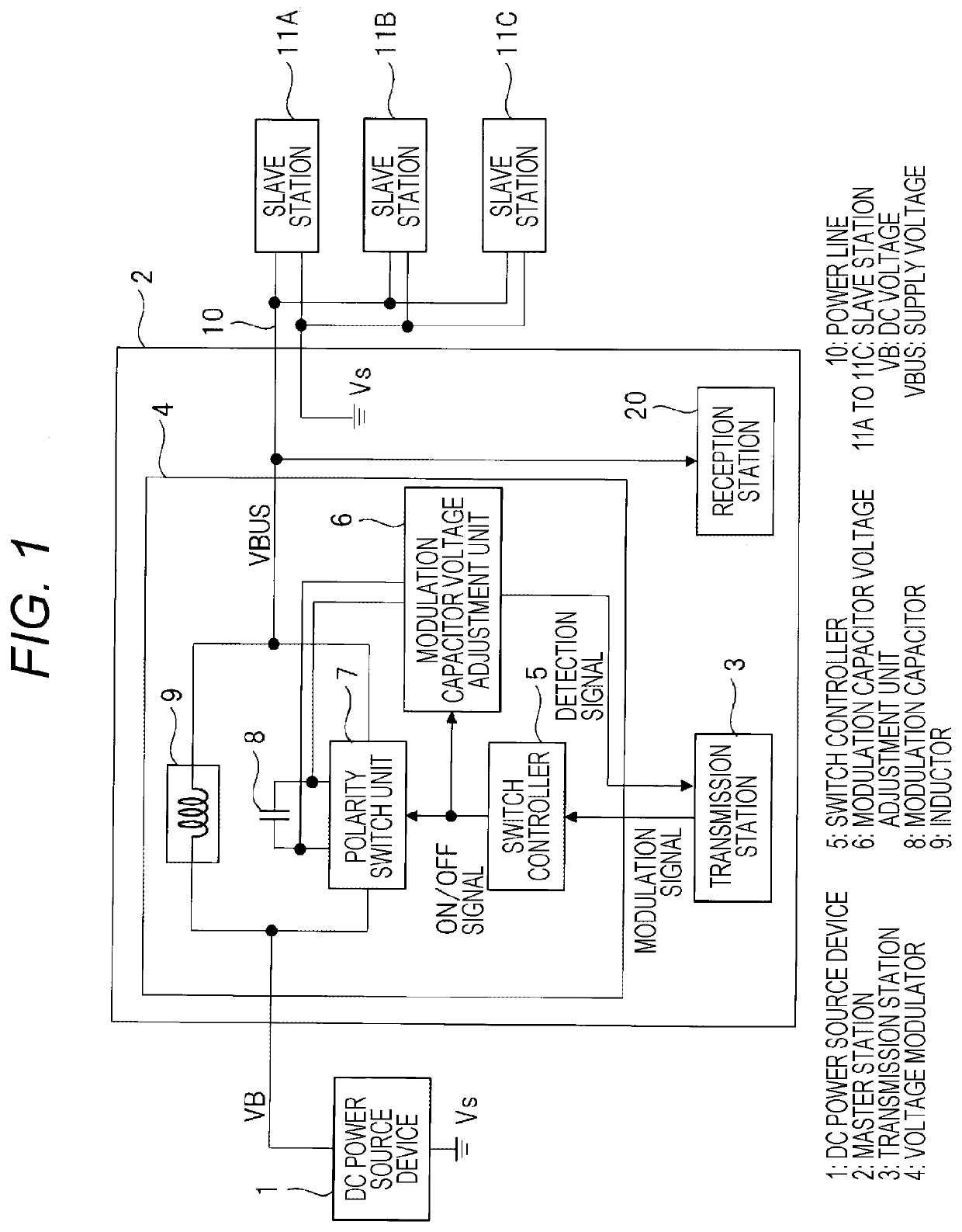
[0025]First, an in-vehicle system will be described using an automobile as an example. FIG. 9 is a diagram illustrating a configuration of the in-vehicle system according to a first embodiment. In FIG. 9, reference numeral 70 denotes an ECU (in-vehicle device) mounted on an automobile 80, 71A to 71C denote actuators, and 72 denotes a battery. Although a large number of sensors and actuators are mounted on the automobile 80, FIG. 9 illustrates only three actuators 71A to 71C among these sensors as representatives. The battery 72 is connected to the ECU 70 by a power source line 73, and is a DC power source that supplies power to the ECU 70 using a battery voltage as a power source voltage.

[0026]The ECU 70 is connected to the actuators 71A to 71C by a power line 10. In the drawing, the power line 10 is drawn as one line, but is configured by a pair of two wires. The ECU 70 supplies a DC voltage supplied from the battery 72 to the actuators 71A to 71C via the power line 10. Altho...

second embodiment

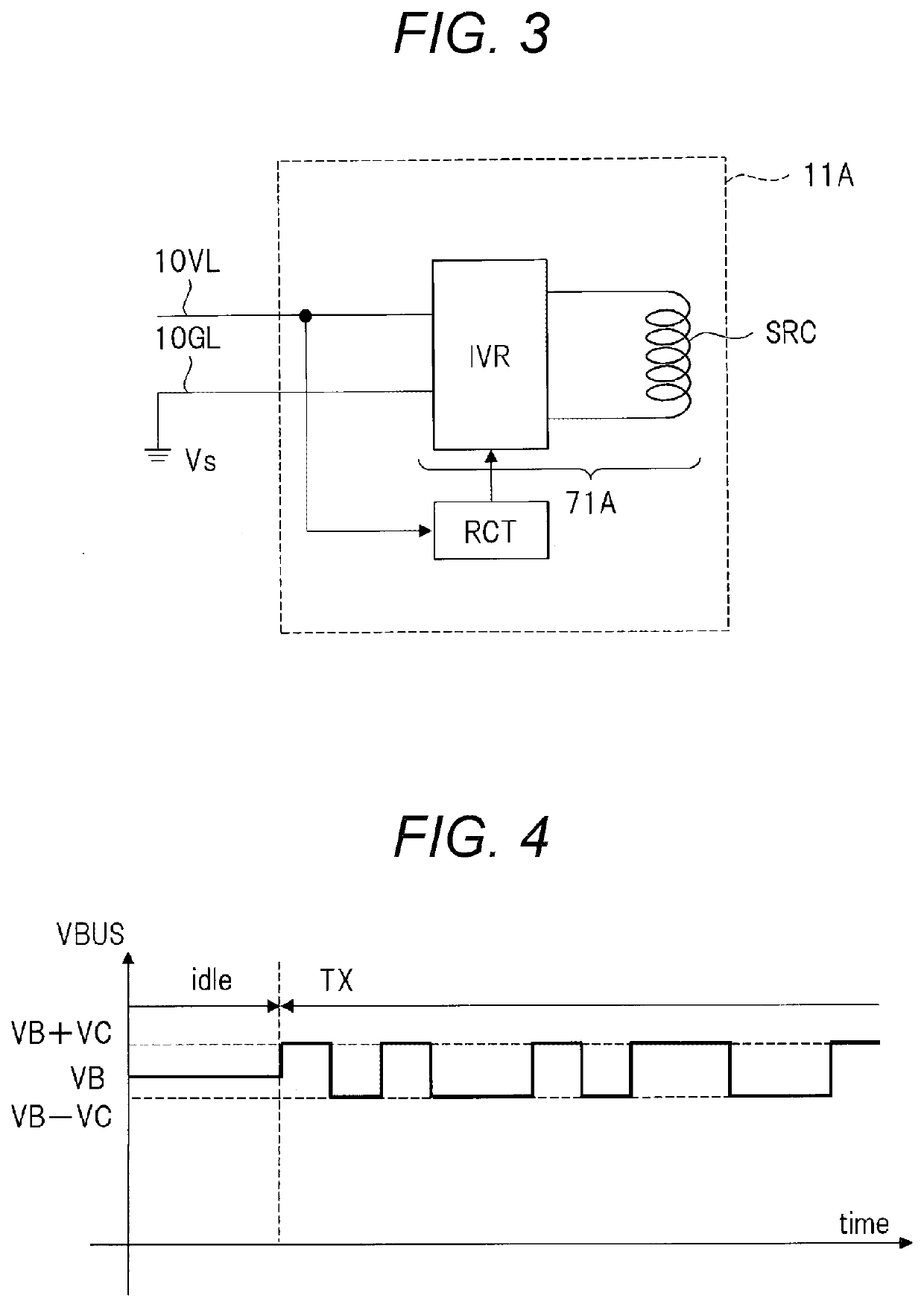
[0070]In the first embodiment, the charging of the modulation capacitor 8 is performed during a period when transmission is not performed (for example, the idle period idle), but it is desirable that the charging be performed during the transmission period to stabilize the holding voltage of the modulation capacitor 8. In the voltage fluctuation during the transmission period TX (FIG. 4) and / or transmission during a long transmission period, for example, the charge held in the modulation capacitor 8 decreases, and the modulation amplitude voltage VC which is the holding voltage of the modulation capacitor 8 becomes unstable. Therefore, it is desirable to stabilize the holding voltage of the modulation capacitor 8 even during the transmission period.

[0071]The second embodiment provides a technique for stabilizing the holding voltage of the modulation capacitor 8 even during the transmission period. FIG. 5 is a block diagram illustrating a configuration of a main part of a master stat...

third embodiment

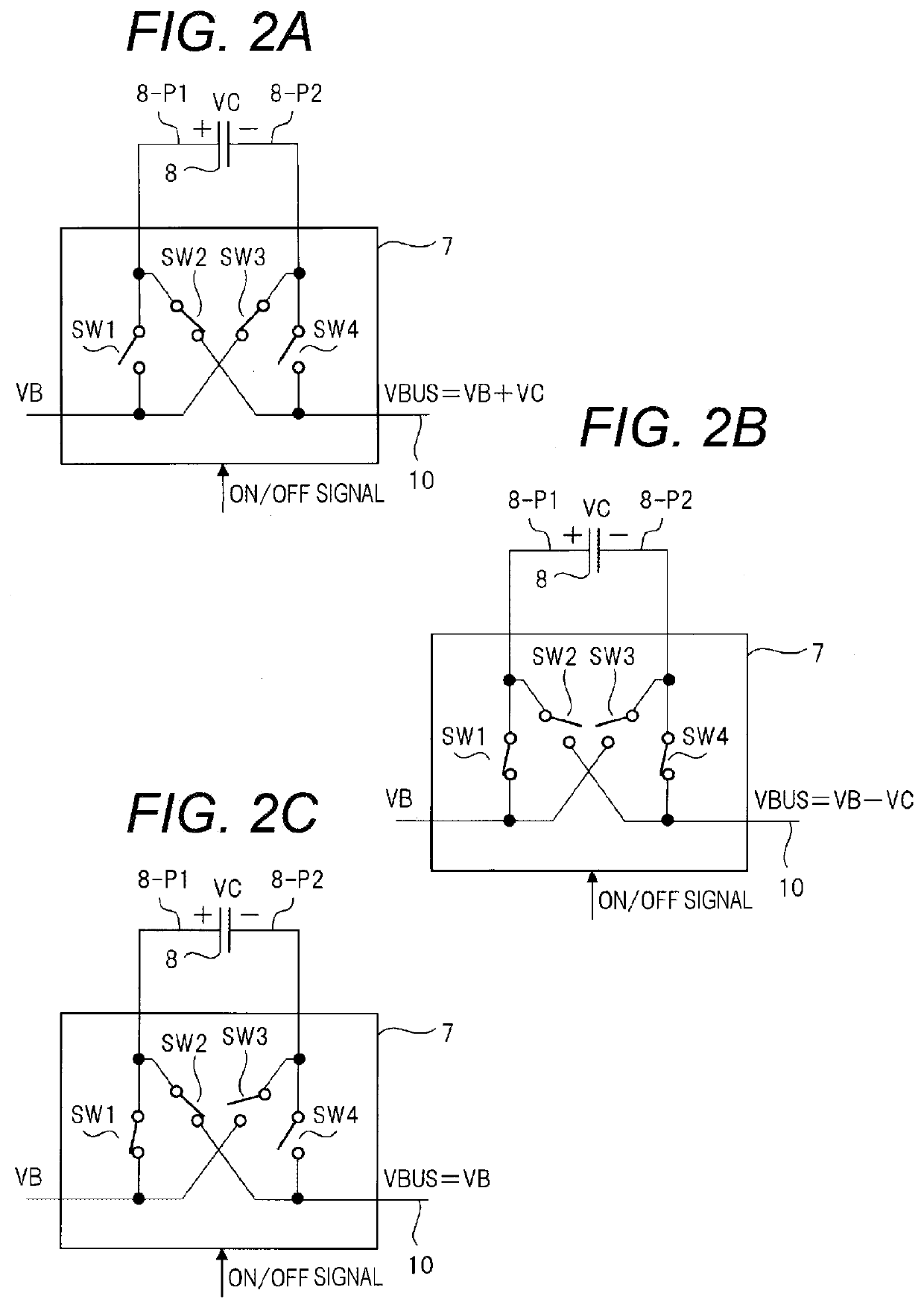
[0092]As described in FIG. 6, the modulation capacitor voltage adjustment unit 6 can discharge the modulation capacitor 8 when modulating the supply voltage VBUS to the H level, and can charge the modulation capacitor 8 when modulating the supply voltage VBUS to the L level. In this case, the time during which the modulation capacitor 8 is charged or discharged depends on the time of the charge signal chg and the discharge signal dhg output from the voltage comparator 61 and the period during which the supply voltage VBUS is at the L level and the H level. That is, by adjusting not only the charge or discharge instruction (charge signal or discharge signal) for the modulation capacitor 8 by the modulation capacitor voltage adjustment unit 6, but also the period when the supply voltage VBUS is at the H level and the period when the supply voltage VBUS is at the L level, the adjustment can adjust the holding voltage of the modulation capacitor 8.

[0093]In other words, by extending the ...


PUM


Abstract

A power line communication device includes a DC power source device, a power line, and a master station that modulates a supply voltage VBUS supplied to the power line according to transmission data to be transmitted. The master station includes a modulation capacitor that is precharged with a modulation amplitude voltage, a polarity switch unit that determines a polarity of the modulation capacitor connected to the power line according to transmission data, and an inductor connected between the DC power source device and the power line.

Description

DEVICE AND IN-VEHICLE SYSTEMTechnical Field[0001]The present invention relates to a power line communication device, an in-vehicle device, and an in-vehicle system, for example, a power line communication device mounted on a vehicle such as an automobile.BACKGROUND ART[0002]In recent years, in automobiles, with the increase in precision and functionality of vehicle control by an electronic control unit (Electronic Control Unit: hereinafter referred to as ECU), there are a number of sensors and actuators to acquire various vehicle information including peripheral information of the vehicle, and to control various parts of the vehicle. Along with this, the number of wires for electrically connecting sensors and actuators to the ECU has been significantly increased. When the number of wires increases, the manufacturing cost of the automobile increases, and furthermore, the fuel consumption deteriorates due to the increase in the vehicle weight. Therefore, it is required to reduce the n...

Claims


Application Information

Patent Timeline
Patent Type & Authority Applications(United States)
IPC IPC(8): H04B3/54
CPCH04B2203/547H04B3/548H04B3/544H04B2203/5412H04B2203/5483H04B2203/5416H04B2203/5495B60R16/023H04B3/54
Inventor YANO, TOMOHIKO
Owner HITACHI ASTEMO LTD
Why Eureka
Try Eureka