

Donor corneal cutting blade
a cutting blade and cornea technology, applied in the field of corneal implants, can solve problems such as complicated marking procedures
- Summary
- Abstract
- Description
- Claims
- Application Information
AI Technical Summary
Benefits of technology
Problems solved by technology
Method used
Image

Examples
Embodiment Construction
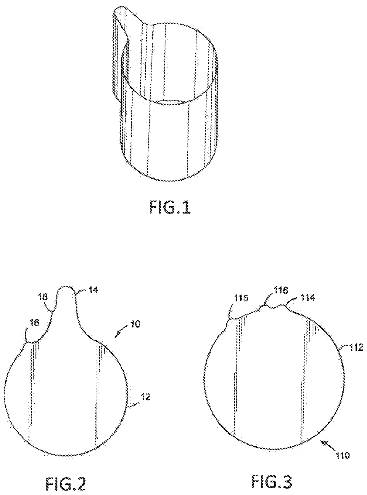
[0015]In accordance with the present invention, there is provided a donor corneal tissue cutting blade provided with integrally formed with a marker or means for marking which enable or facilitate identification of the anterior and posterior sections or portions of the donor corneal tissue to enable proper placement in the anterior cavity of the recipient.
[0016]Now, and with reference to the drawing and, FIGS. 1 and 2, there is depicted therein, a first embodiment hereof which is predicated on a Bala Punch corneal donor cutting blade, and, which is, generally, denoted at 10. A “Bala Punch” is a donor corneal cutting blade which has been developed by Dr. Chandrashekar Balachandran and has been disclosed at professional meetings and is presently being readied for commercial availability.
[0017]The blade 10 hereof, has a substantially cylindrical body 12 and a U-shaped extension or “tail”14 integrally formed therewith. The body and tail cooperate to form a keyhole or keyway, as shown.
[0...
PUM
 Abstract
Description
Claims
Application Information