Tensioner lever

US20210156456A1Active Publication Date: 2021-05-27TSUBAKIMOTO CHAIN CO
0 Cites 2 Cited by

Patent Information

Authority / Receiving Office
US · United States
Current Assignee / Owner
Publication Date
2021-05-27

Smart Images

  • Figure 1
    Figure 1
  • Figure 2
    Figure 2
  • Figure 3
    Figure 3
Patent Text Reader

Abstract

An object of the present invention is to provide a tensioner lever that can reduce vibration and noise when the chain runs, and realize smooth attachment into an engine with minimal deformation of the lever body with a simple configuration. A tensioner lever according to the present invention includes a lever body and a torsion coil spring pressed the lever body toward the chain. The lever body includes a stopper member mounting part where a stopper member by which the support arm of the torsion coil spring is locked and which retains the torsion coil spring in a compressed state is removably mounted. The stopper member mounting part is located closer to a distal end of the lever body than a center position in the longitudinal direction of the lever body, or a center of gravity position of the lever body.
Need to check novelty before this filing date? Find Prior Art

Description

BACKGROUND OF THE INVENTION1. Field of the Invention

[0001] The present invention relates to a tensioner lever that slidably guides a running chain, and more particularly to a chain tensioner lever that slidably guides a chain by pressing a shoe surface of a lever body against the chain by the resilient force of a torsion coil spring.2. Description of the Related Art

[0002] Tensioner levers have been used in chain transmissions for an auxiliary machine or the like of a car engine to remove slackness in chains and to prevent vibration of running chains. One such known tensioner lever, which is pivotably attached to an attachment surface of an engine block or the like, includes a lever body having a shoe surface that slidably guides the chain, and a torsion coil spring interposed between the lever body and the attachment surface to press the shoe surface toward the chain (see, for example, Japanese Patent Application Laid-open Nos. 2009-108909, 2016-160985, and 2017-115952).

[0003] These te...

Examples

Embodiment Construction

[0020]A tensioner lever that is one embodiment of the present invention will be hereinafter described with reference to the drawings.

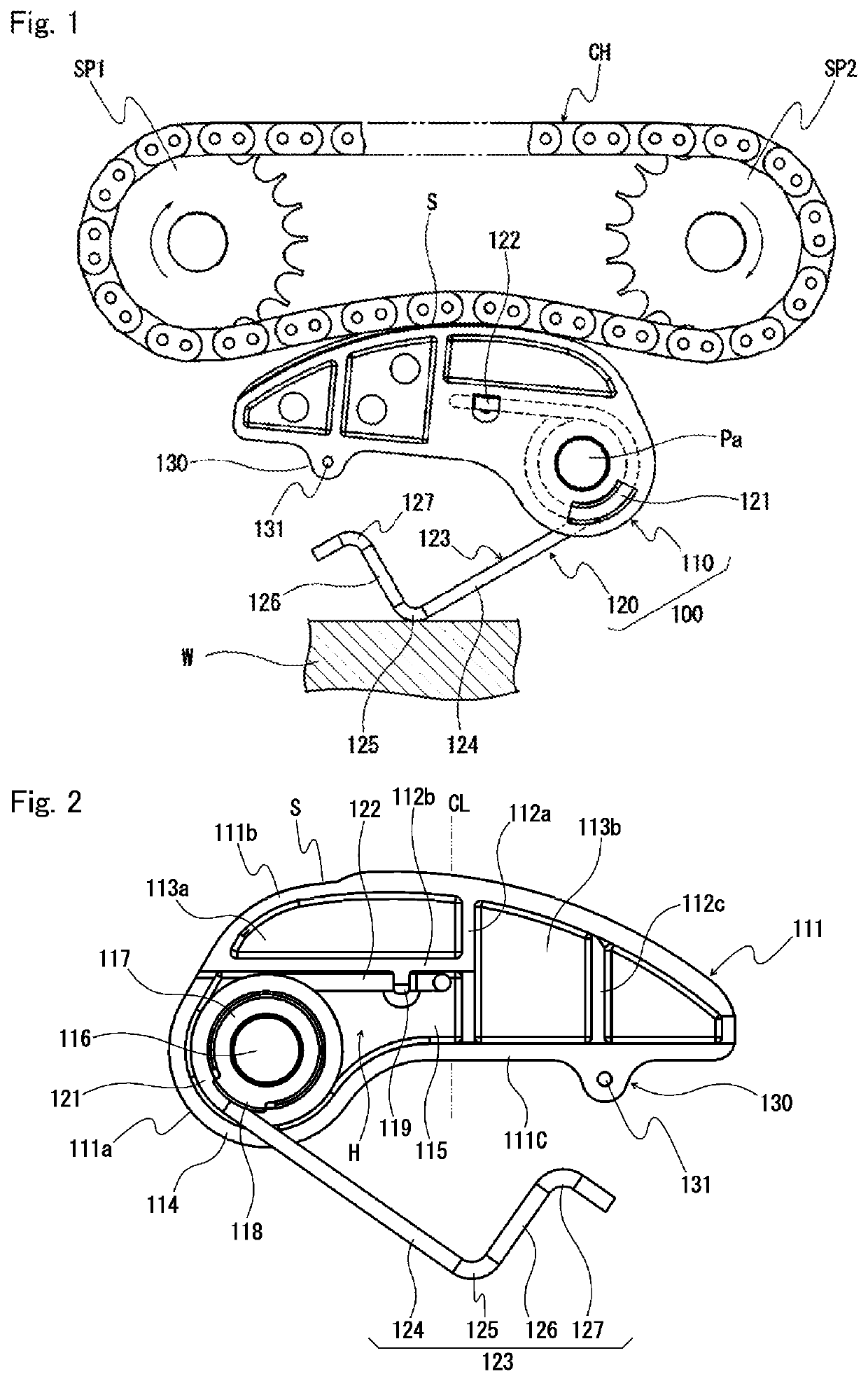
[0021]The tensioner lever 100, as shown in FIG. 1, is pivotably mounted on a pivot shaft Pa protruding from an attachment surface (not shown) of an engine block (not shown) or the like to slidably guide a chain CH passed over between a drive-side sprocket SP1 attached to a crankshaft and a driven-side sprocket SP2 attached to a shaft of an auxiliary machine to keep an appropriate chain tension.

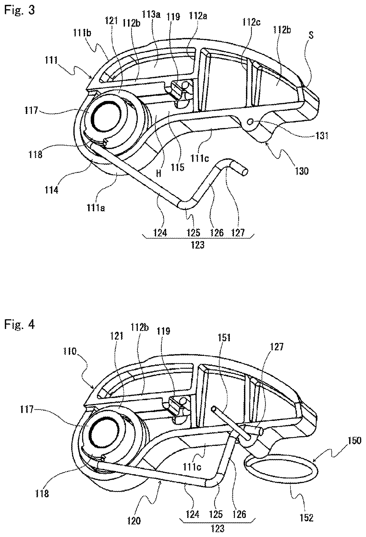
[0022]The tensioner lever 100 includes a lever body 110 having a shoe surface S formed along a longitudinal direction for slidably guiding the chain CH and a base end rotatably supported on an attachment surface, and a torsion coil spring 120 interposed between the lever body 110 and the attachment surface to press the shoe surface S toward the chain CH. As illustrated in FIG. 1, the resilient force of the torsion coil spring 120 exerts a torque on the lever body...