Probe pin and electronic device with same

A probe and electroforming technology, applied in the direction of measuring electricity, measuring electrical variables, components of electrical measuring instruments, etc., can solve the problems of unsuitable miniaturization, lengthening of elastic parts, and narrowing of the interval of elastic parts, etc. Effects of degrees of freedom

Inactive Publication Date: 2017-05-31
ORMON CORP
View PDF7 Cites 4 Cited by
  • Summary
  • Abstract
  • Description
  • Claims
  • Application Information

AI Technical Summary

Problems solved by technology

[0009] However, in the above-mentioned probes, the space between the elastic parts becomes narrow when miniaturization is performed, and the elastic parts become long if a sufficient stroke is to be obtained. Therefore, there is a problem that it is not suitable for miniaturization.

Method used


Image

  • Probe pin and electronic device with same
  • Probe pin and electronic device with same
  • Probe pin and electronic device with same

Examples


specific Embodiment approach

[0065] Hereinafter, embodiments of an inspection unit including a probe of the present invention will be described with reference to the drawings. In addition, in the following description, terms indicating directions such as "upper", "lower", "left", "right" and other terms including them are used to describe the structures shown in the drawings, but these The purpose of the terms is to facilitate understanding of the embodiments through the drawings. Therefore, these terms only show the direction when the embodiments of the present invention are actually used, and these terms should not be used to limitably interpret the technical scope of the invention described in the scope of claims.

no. 1 approach

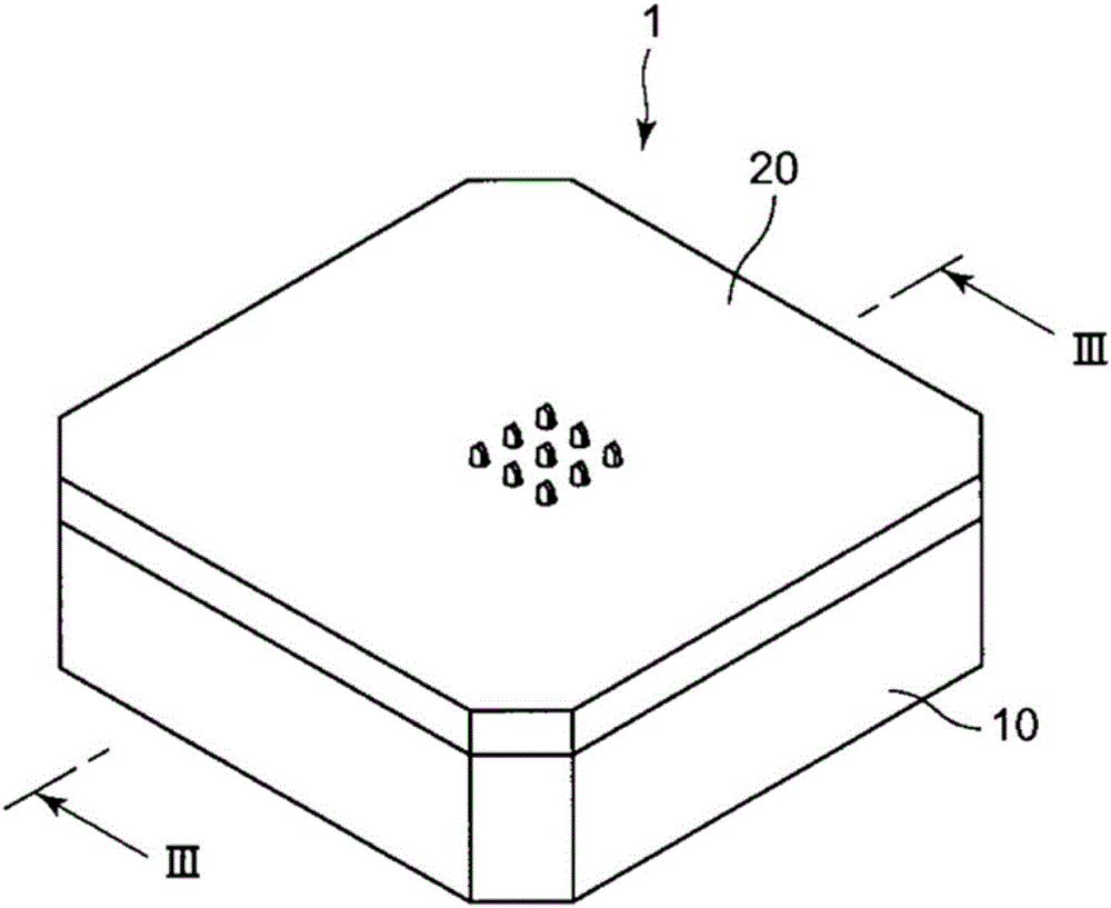
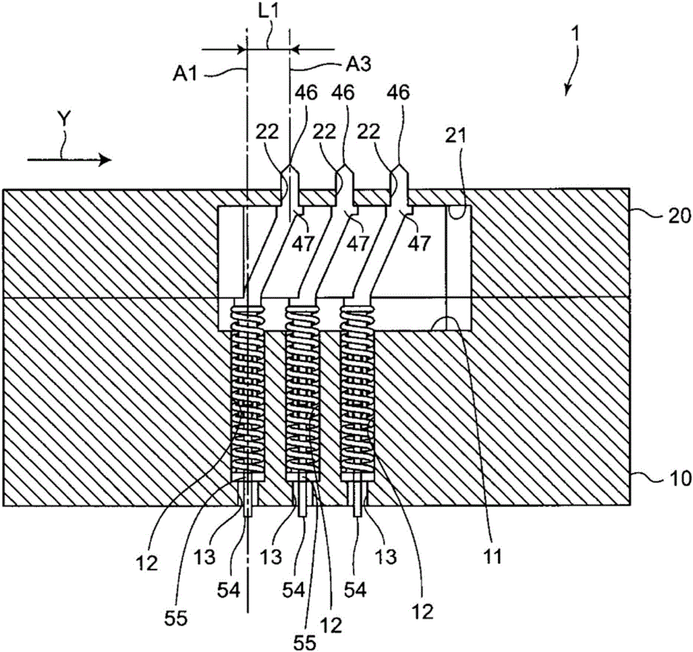
[0067] figure 1 It is a perspective view of an example of an inspection unit equipped with a probe according to the first embodiment of the present invention, figure 2 is to remove figure 1 A perspective view showing the state of a part of the inspection unit, image 3 is along figure 1 Sectional view of line III-III.

[0068] like Figure 1 ~ Figure 3 As shown, the inspection unit 1 as an example of electronic equipment includes a case and the probe 30 of the first embodiment accommodated in the case. The housing is composed of a housing main body 10 and a housing cover 20 covering the housing main body 10 , and the probe 30 is housed in the housing main body 10 .

[0069] like figure 2 As shown, the case main body 10 has a planar shape in which four corners of a square are chamfered in plan view. A concave portion 11 is provided substantially at the center of the upper surface of the housing body 10 .

[0070] A plurality of housing portions 12 for housing the prob...

no. 2 approach

[0102] Figure 8 ~ Figure 13 It is a figure which shows an example of the probe 230 of 2nd Embodiment, and the inspection unit 201 provided with the probe 230 of 2nd Embodiment. In this second embodiment, the same reference numerals are assigned to the same parts as those in the first embodiment, and description thereof will be omitted, and points different from the first embodiment will be described. In addition, the inspection unit 201 is an example of electronic equipment.

[0103] like Figure 10 ~ Figure 13 As shown, the probe 230 of the second embodiment extends in the middle part 242 of the first plunger 140 along a direction that is 90 degrees relative to the long side direction of the clamped part 41, and the contact part 43 extends along the direction relative to the middle The portion 142 is different from the probe 30 of the first embodiment in that the longitudinal direction of the portion 142 extends in a direction 90°. That is, the probe 230 is configured suc...


PUM


Abstract

A probe pin (30) is provided with: at least one coiled spring (60) extending and contracting along the centerline; a first contact point (46) disposed on a first straight line (A3) parallel to the centerline of the coiled spring (60); and a second contact point (54) disposed on a second straight line (A1) coinciding with the centerline of the coiled spring (60). The first and second contact points (46, 54) are supported so as to be capable of being reciprocated by the force of the coiled spring (60) and are conducted directly to each other.

Description

technical field [0001] The present invention relates to a probe and electronic equipment equipped with the probe. Background technique [0002] In the manufacturing process of semiconductor devices and LSI (Large Scale Integration), etc., an electrical test is performed using electronic equipment equipped with probes to check whether they function normally. In the electronic equipment used in this energization test, a so-called straight-type probe in which contacts at both ends reciprocate along the same straight line is generally used. [0003] However, in the above-mentioned energization test, the object to be inspected such as a semiconductor device and the inspection device are electrically connected by probes. However, with the diversification of inspection devices and inspection objects, it is difficult to linearly connect the inspection object and inspection devices, and it is increasingly difficult to cope with linear probes. As one method of solving such a problem...

Claims


Application Information

Patent Timeline
Patent Type & Authority Applications(China)
IPC IPC(8): G01R1/067G01R1/073G01R31/26H01L21/66
CPCG01R1/067G01R1/073G01R31/26
Inventor 寺西宏真酒井贵浩
Owner ORMON CORP
Why Eureka
Try Eureka