
Piezoelectric air valve and multiple-type piezoelectric air valve

a piezoelectric air valve and piezoelectric technology, applied in the direction of valve operating means/releasing devices, mechanical equipment, transportation and packaging, etc., can solve the problems of increasing the mass of the moving armature itself, not having a satisfactory high-speed performance required for air valves, and not having a satisfactory high-speed performan

Active Publication Date: 2004-10-21
MECHANO TRANSFORMER CORP +1
View PDF40 Cites 20 Cited by
  • Summary
  • Abstract
  • Description
  • Claims
  • Application Information

AI Technical Summary

Benefits of technology

The present invention relates to a granular material sorting machine for sorting and removing foreign materials such as stones and defectives. The main technical effect of the invention is to improve the high-speed performance of the air valve in the sorting machine by using an air valve functioning as the main component. The current air valve used in the sorting machine has limitations in its high-speed performance due to the electromagnetic attraction force and magnetic saturation. The invention proposes to use a piezoelectric element to generate force for opening and closing the air valve, which has a higher response speed than the current electromagnetic attraction force. However, the quantity of displacement generated by the piezoelectric element is too small to be used for the air valve. The invention proposes to use a combination of the piezoelectric element and a diaphragm to overcome this limitation and achieve efficient and high-speed operation of the air valve.

Problems solved by technology

However, in practice, the sorting machine blows way not only the defectives but also normal granular materials sometimes. This is an unfavorable phenomenon that results in, and it is noted as one of the reasons that the air valve does not have a satisfactory high-speed performance required for the selective removal.
However, the air valve utilizing the electromagnetic attraction force has already reached its maximum capability and has no more allowance for the high-speed operating performance for reasons of the followings.
However, the increase in the mass of the moving armature itself runs counter to the further high-speed operation thereof.
Hence, it is noted that the operation of the air valve of the type utilizing the electromagnetic attraction force at a high speed faster than the speed having been achieved at present will be so hard to realize.
However, the quantity of the displacement to be generated by the piezo-element is at most in a range of ten and several .mu.m to several tens .mu.m, which is too small to be used for the air valve used in the sorting machine that performs control operations to open and close the compressed air.
However, the force itself generated by the displacement of the piezoelectric element is little, and the air valve of this type cannot respond quickly.
Hence, the air valve of this type has not been used with satisfaction for the opening / closing control of the air valve to which the high-speed response performance is intensively required.
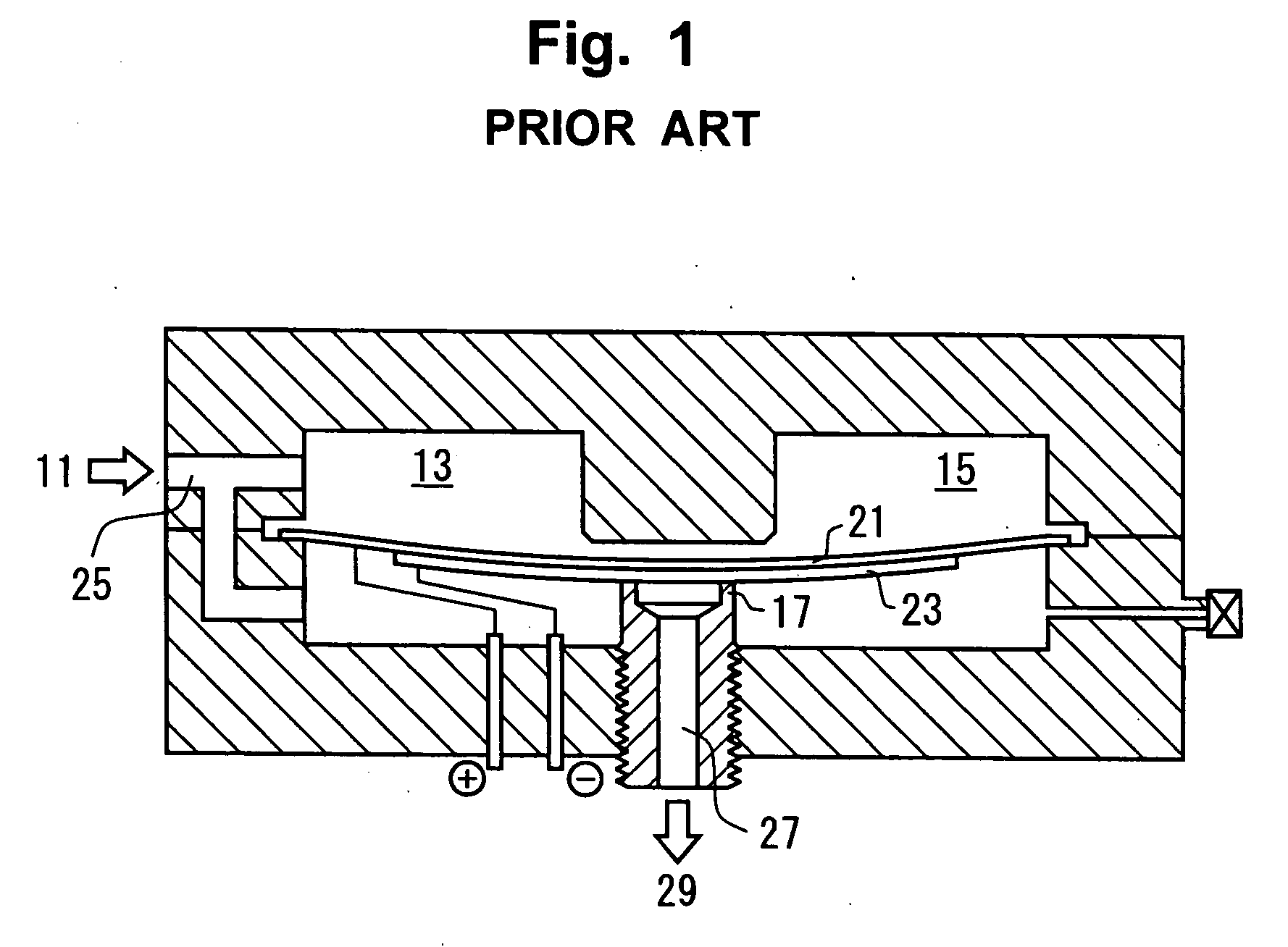
As a result, there is a problem for the air valve of this type in that it cannot give sufficient air pulses 29, especially in the response performance.
However, there is such a defective in this on / off valve that it takes time for the closing operation of the flapper valve after the impact because the closing operation is effected by a spring with weak elasticity.
However, it takes time with this valve for the closing operation like the valves of the prior art do since the closing operation of the valve is effected by an elastic member (a spring) for resetting unlike the piezoelectric element.
Although there could be problematic in the response performance and the abrasion property if the movable access shaft of a sliding type is formed, this elimination device has such a special structure that it uses the bounce of a permanent magnet to float the movable access shaft to thereby support the movable access shaft without sliding.
However, since the permanent magnet is structurally required for floating the movable access shaft to support it, the size of the elimination device alone becomes large to a given extent.

Method used


Image

  • Piezoelectric air valve and multiple-type piezoelectric air valve
  • Piezoelectric air valve and multiple-type piezoelectric air valve
  • Piezoelectric air valve and multiple-type piezoelectric air valve

Examples


Embodiment Construction

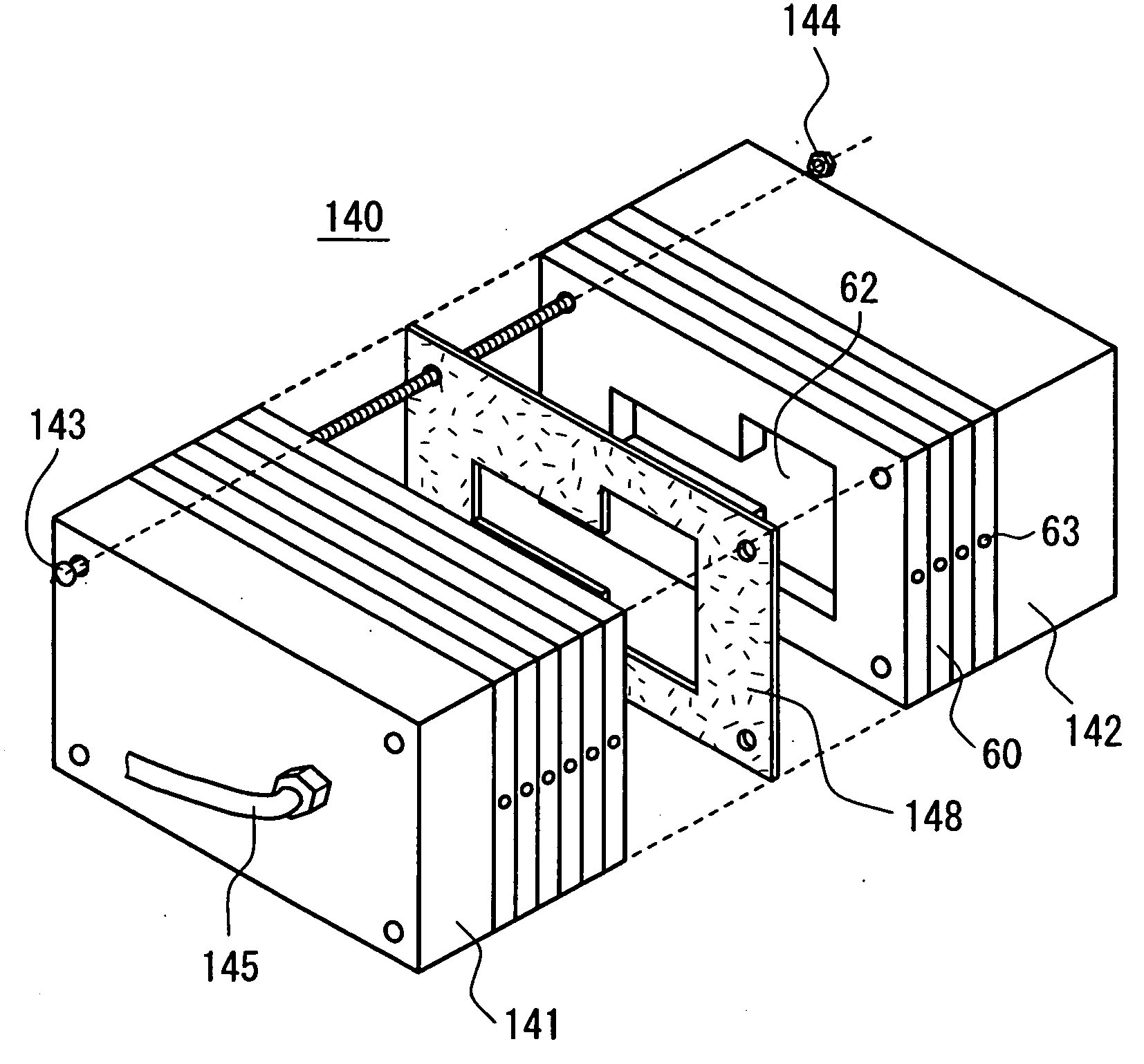
[0039] Now, the piezoelectric air valve and the multiple-type piezoelectric air valve according to the present invention will be described in detail in the following with reference to the appended drawings.

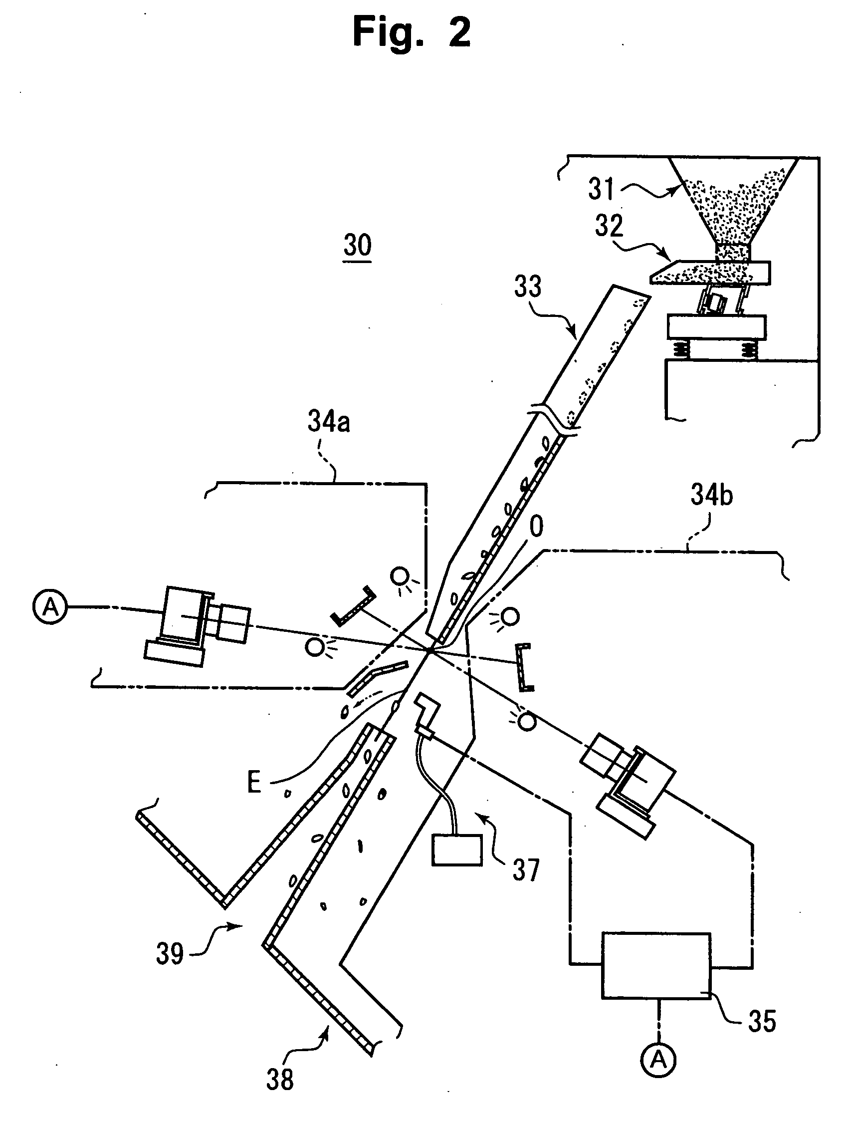
[0040] In the first place, the outline of a granular material sorting machine that can use the piezoelectric air valve according to the present invention will be explained with reference to FIG. 2 in order to help understanding of the present invention. FIG. 2 is a schematic cross-sectional side view of the main portion of the granular material sorting machine 30 and the internal structure thereof. The granular material sorting machine 30 includes on its upper portion a granular material feeding section comprising a tank 31 and a vibrating feeder 32. The granular materials fed from the granular material feeding section naturally flow down in series through an inclined chute 33 and then released into air from its lower end portion along a given falling locus.

[0041] In the surroundi...


PUM


Abstract

The air valve includes a valve body for controlling operations to open and close the communication between an air pressure chamber and an air outlet, a piezoelectric element for generating driving force in the form of displacements, and a displacement enlarging mechanism for enlarging the small displacements generated by the piezoelectric element by the principle of a pry and applying the enlarged displacements to the valve body. The enlarged displacements cause a large and sufficient gap to be developed between the air pressure chamber and the air outlet when a voltage is applied to the piezoelectric element. When the applying of voltage to the piezoelectric element is stopped, the resetting force of the piezoelectric element itself causes the gap to be closed quickly.

Description

[0001] This application relates to and claims a priority from corresponding Japanese Patent Application No. 2003-113786 filed on Apr. 18, 2003.[0002] 1. Field of the Invention[0003] The present invention relates to a granular material sorting machine for sorting and removing foreign materials such as stones undesirably mixed in cereals like rice grains and defectives such as colored grains and, more specifically, to an air valve functioning as the main component which affects the sorting capability in the granular material sorting machine.[0004] 2. Description of the Related Art[0005] In general, elimination of defectives by means of a sorting machine is carried out by contiguously releasing granular materials into air along a given falling locus and blowing away the defectives at a predetermined position outside the given falling locus with use of air pulses in accordance with a defective detection signal. It is an air valve to generate the air pulses that directly blow away the de...

Claims


Application Information

Patent Timeline
Patent Type & Authority Applications(United States)
IPC IPC(8): F16K31/00F16K31/02
CPCF16K31/006F16K31/004B07C5/363Y10T137/87877B07C5/00
Inventor YANO, TAKESHIHIGUCHIKUDOH, KENICHICHEE, SZE KEATSHIBATA, TSUNEHIKOIKEDA, NORIMASA
Owner MECHANO TRANSFORMER CORP
Learn More