Process for producing acetic acid

a technology of acetic acid and process, which is applied in the preparation of carboxylic compounds, carbon monoxide reaction carboxylic preparations, organic chemistry, etc., can solve the problems of deteriorating product quality, affecting the quality of acetic acid, and impurities exerting bad influence, so as to achieve stably production and high purity, the effect of efficiently removing acetaldehyd

Active Publication Date: 2015-01-27
DAICEL CHEM IND LTD
View PDF12 Cites 44 Cited by
  • Summary
  • Abstract
  • Description
  • Claims
  • Application Information

AI Technical Summary

Benefits of technology

[0031]According to the present invention, acetic acid (acetic acid with a high purity) can stably be produced while efficiently removing acetaldehyde by adjusting the amount of the lower boiling point component to be stored in the decanter in response to the fluctuation of the feed amount of the lower boiling point component containing methyl iodide and acetaldehyde. Moreover, according to the present invention, since acetaldehyde can be separated from the lower boiling point component efficiently and reliably, acetic acid can be produced while highly efficiently recycling the co-catalyst, methyl iodide, separated from the lower boiling point component.

Problems solved by technology

As the production of acetic acid increases, the production of the impurities increases, which deteriorates the quality of acetic acid.
For example, in a quality test by which the very minute amounts of the reducing impurities present in acetic acid are checked, which is called a permanganate-reducing substance test (permanganate time), impurities having very slight concentrations, which are hard to quantitatively determine even with today's highly advanced instrumental analysis, can be detected, and these impurities lead to deterioration of product quality.
Moreover, some of these impurities exert a bad influence in connection with use of acetic acid.
Unfortunately, the carbonyl compound or the alkyl iodide is hard to remove sufficiently by ordinary means, such as distillation, because the boiling point of the carbonyl compound or the alkyl iodide is close to a boiling point of an iodide catalyst accelerator, or other reasons.
Because the treatment has the limitation on the concentrations of impurities to be treated, the carbonyl compound and the organic iodide cannot be removed efficiently.
The concentration of the carbonyl impurity in the organic stream to be recycled to the carbonylation reactor is still high, and it is difficult to remove the carbonyl impurity sufficiently.
Incidentally, this document does not disclose that the flow rate of the overhead is controlled in recirculating the overhead into the reactor.

Method used


Image

  • Process for producing acetic acid
  • Process for producing acetic acid

Examples


example 1

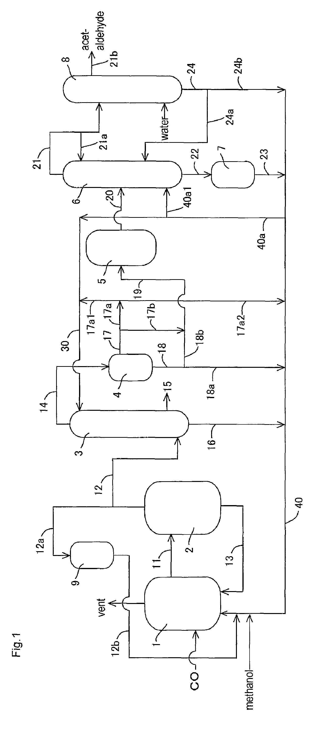
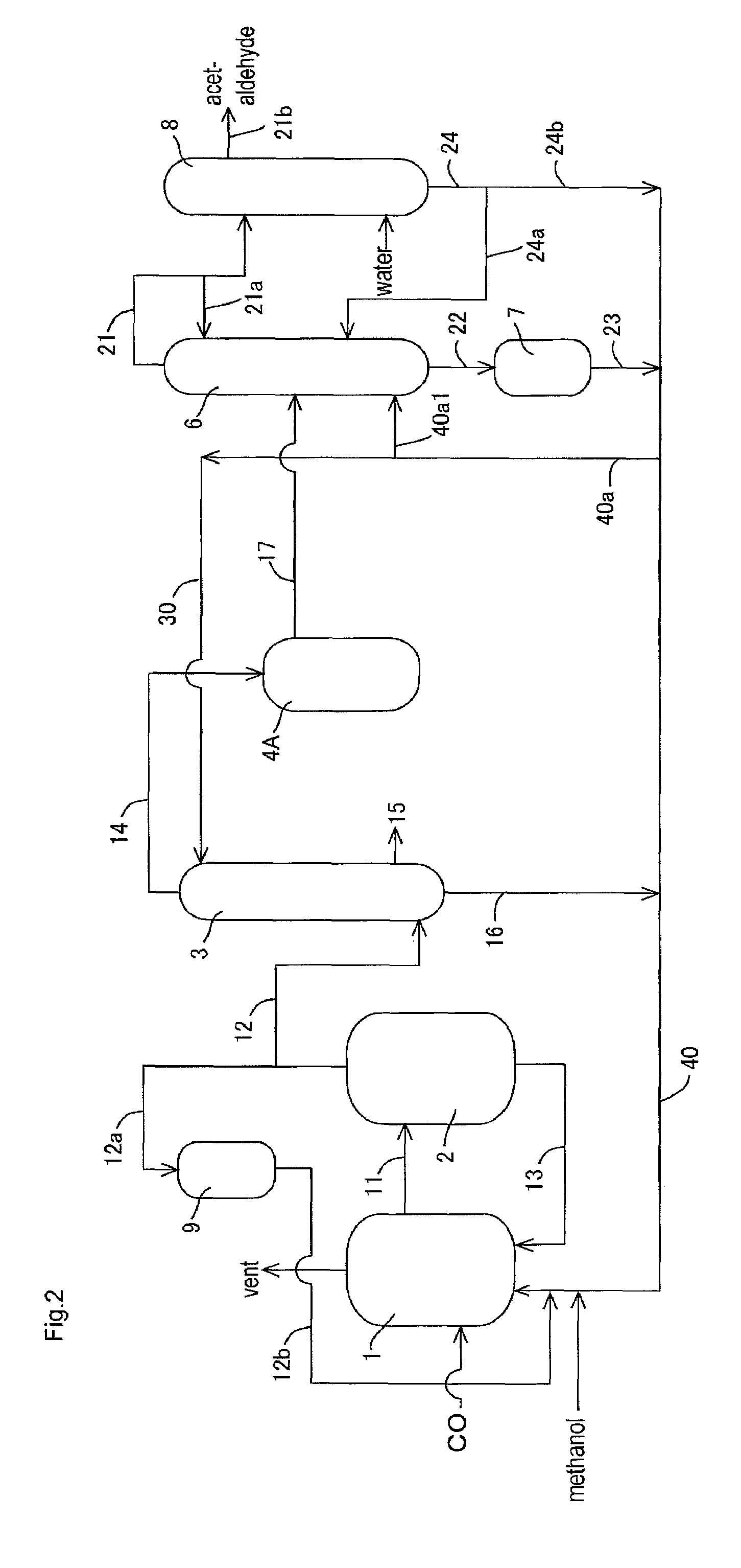
[0149]In the apparatus (or process) of FIG. 1, acetic acid production process was carried out continuously as shown in FIG. 1 except that the lower boiling point component (3A) was fed to the acetaldehyde separation column 6 without going through the buffer tank 5. The detail of the process will be described below.

[0150]A liquid reaction medium had the following composition (or formulation): methyl iodide (13% by weight), water (8% by weight), methyl acetate (1.3% by weight), acetic acid (73.6% by weight), lithium iodide (5% by weight), and rhodium (800 ppm by weight). The liquid reaction medium was fed to the reactor 1, and the process was started. Throughout the process, the variation in the flow rate of the liquid reaction medium fed from the reactor 1 to the flasher 2 was in the range of about ±1.6% relative to the average flow rate. In the flasher 2, about 27% by weight of the total liquid reaction medium was fed to the splitter column 3 as the lower boiling point component (2A...

example 2

[0161]Example 2 was conducted in the same manner as in Example 1 except that part of the lower boiling point component (3A) discharged from the decanter 4 was recycled and that the rest was fed to the distillation column 6 in the process as described later.

[0162]With respect to the lower boiling point component (3A) of the upper layer, the proportion of the lower boiling point component (3A) fed to the line 19 (or the line 17b) was 0% by volume in the total lower boiling point component (3A) fed to the decanter 4 (that is, the lower boiling point component (3A) of the upper layer is wholly recycled without being fed to the line 19 or the line 17b); with respect to the lower boiling point component (3A) of the lower layer, the proportion of the lower boiling point component (3A) fed to the line 19 (or the line 18b) was 27% by volume (corresponding to 57% by volume of the whole lower layer) in the total lower boiling point component (3A) fed to the decanter 4.

[0163]That is, 27% by vol...

example 3

[0169]Example 3 was conducted in the same manner as in Example 1 except that part of the lower boiling point component (3A) discharged from the decanter 4 was recycled and that the rest was fed to the distillation column 6 in the process as described later.

[0170]In the same manner as in Example 1, the lower boiling point component (3A) was discharged from an upper part of the decanter 4 (a position corresponding to the upper layer) through the line 17 such that the liquid level and the interface level of the lower boiling point component (3A) to be held in the decanter 4 were maintained substantially constant (such that the fluctuation of the liquid level was about ±1% relative to the average liquid level and the fluctuation of the interface level (or the liquid level of the lower layer) was about ±1% relative to the average interface level). That is, the liquid level and the interface level of the lower boiling point component (3A) in the decanter 4 were maintained substantially co...


PUM

PropertyMeasurementUnit
volume ratioaaaaaaaaaa
partial pressureaaaaaaaaaa

Abstract

A process for stably producing high purity acetic acid comprising a condensation step for condensing and temporarily holding the lower boiling component in a decanter and discharging from the decanter; and a step for separating the lower boiling component discharged from the decanter into acetaldehyde and a liquid residue and recycling the liquid residue to the reaction system. In the condensation step, the amount of the lower boiling component to be held is controlled based on the fluctuating flow rate of the lower boiling component to be fed to the decanter.

Description

TECHNICAL FIELD[0001]The present invention relates to a process for stably producing acetic acid by carbonylation of methanol in the presence of a metal catalyst (such as a rhodium catalyst) and methyl iodide.BACKGROUND ART[0002]Various industrial production processes of acetic acid have been known. Among others, an industrially excellent process includes a process which comprises continuously allowing methanol to react with carbon monoxide with the use of a rhodium catalyst and methyl iodide in the presence of water to give acetic acid. Moreover, recently improvement in reaction conditions and catalysts was investigated, and an industrial process for producing acetic acid with a highly efficient production has been developed by addition of a catalyst stabilizer (such as an iodide salt) and the reaction under a low water content condition compared with the conventional condition. This process enables by-products including carbon dioxide or propionic acid to be reduced because of low...

Claims


Application Information

Patent Timeline
Patent Type & Authority Patents(United States)
IPC IPC(8): C07C51/12C07C51/44
CPCC07C51/12C07C51/44C07C53/08
Inventor SHIMIZU, MASAHIKO
Owner DAICEL CHEM IND LTD
Why Eureka
Try Eureka