Magnetic head comprising magnetic domain control layer formed on ABS-side of magnetic flux guide for GMR element and method of manufacturing the magnetic head

a magnetic head and magnetic domain technology, applied in the field of magnetic detecting elements, can solve problems such as difficulty in appropriate domain control, and achieve the effect of effective control of the magnetic domain

Inactive Publication Date: 2005-04-07
TDK CORPARATION
View PDF10 Cites 19 Cited by
  • Summary
  • Abstract
  • Description
  • Claims
  • Application Information

AI Technical Summary

Benefits of technology

[0018] The present invention has been achieve for solving the above problems of conventional magnetic heads, and an object of the present invention is to provide a magnetic head suitable for miniaturization and capable of effectively controlling the magnetic domain of a magnetic flux guide layer which is magnetically connected to a free magnetic layer, and a method of manufacturing the magnetic head.

Problems solved by technology

Therefore, the shape of the magnetic domain control layer 15 is complicated to cause a difficulty in appropriate domain control.

Method used


Image

  • Magnetic head comprising magnetic domain control layer formed on ABS-side of magnetic flux guide for GMR element and method of manufacturing the magnetic head
  • Magnetic head comprising magnetic domain control layer formed on ABS-side of magnetic flux guide for GMR element and method of manufacturing the magnetic head
  • Magnetic head comprising magnetic domain control layer formed on ABS-side of magnetic flux guide for GMR element and method of manufacturing the magnetic head

Examples


first embodiment

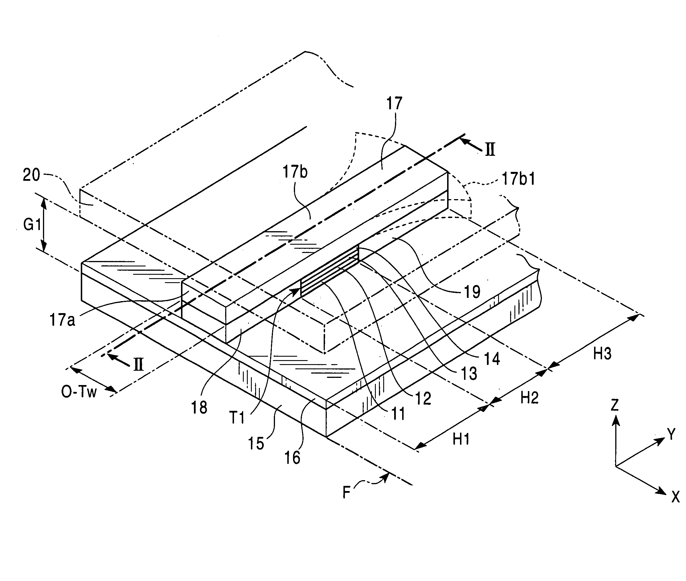
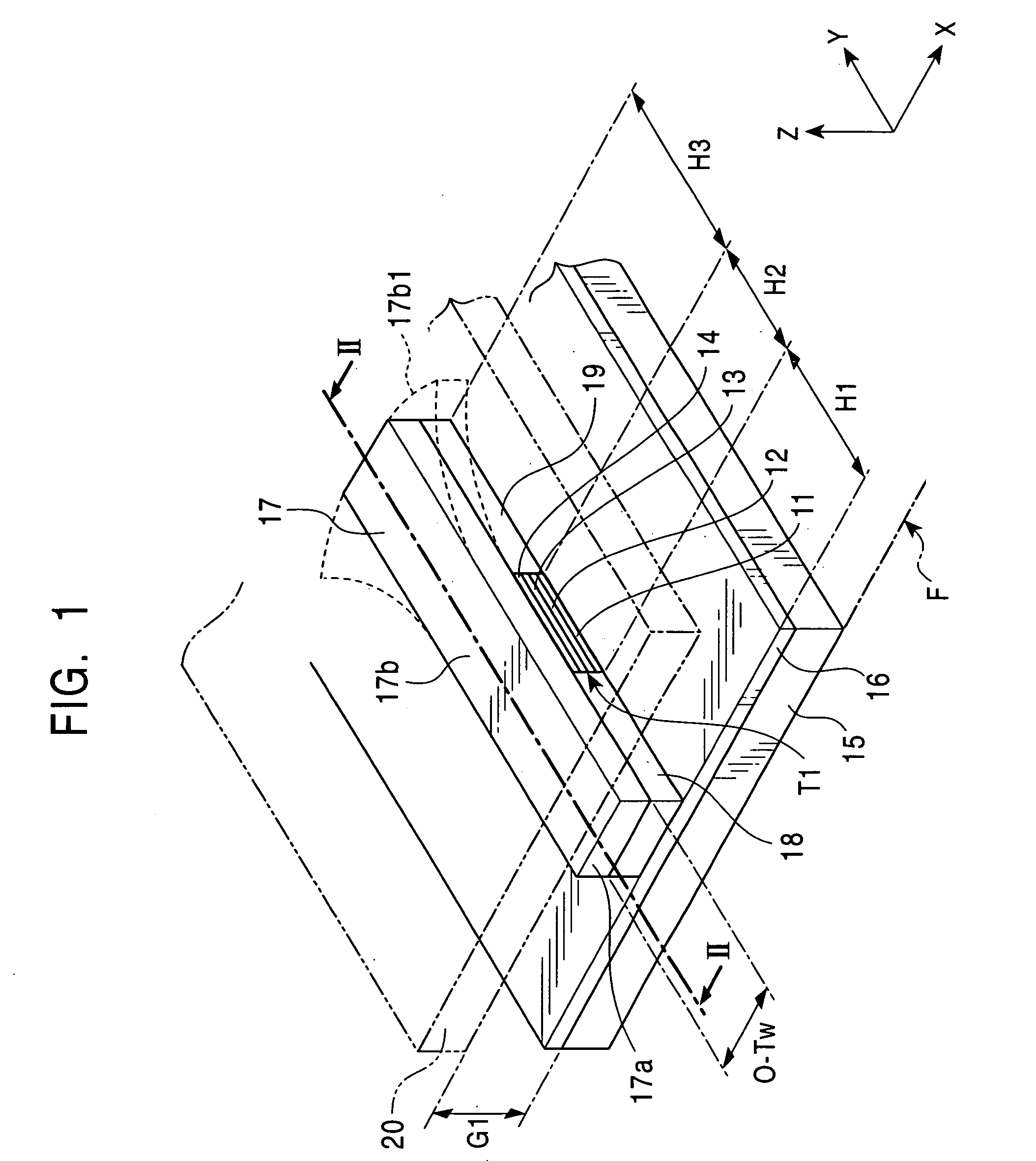
[0095]FIG. 1 is a perspective view schematically showing a magnetic head according to the present invention.

[0096] The magnetic head shown in FIG. 1 is a magnetic head for reproducing a recording signal magnetically recorded on a recording medium.

[0097] In FIG. 1, a multilayer film Ti comprising an antiferromagnetic layer 11, a pinned magnetic layer 12, a nonmagnetic material layer 13, and a free magnetic layer 14 is formed on a lower gap layer 16 laminated on a lower shield layer 15 to be disposed at a predetermined distance Hi from a surface F facing a recording medium in the height direction.

[0098] The multilayer film Ti serves as a magnetic detecting element having a magnetoresistive effect, for example, such as a spin-valve GMR magnetoresistive element or spin-valve tunneling magnetoresistive element. The detailed structure of the multilayer film Ti will be described below.

[0099] Also, a magnetic flux guide layer 17 is connected to the free magnetic layer 14 of the multilaye...

third embodiment

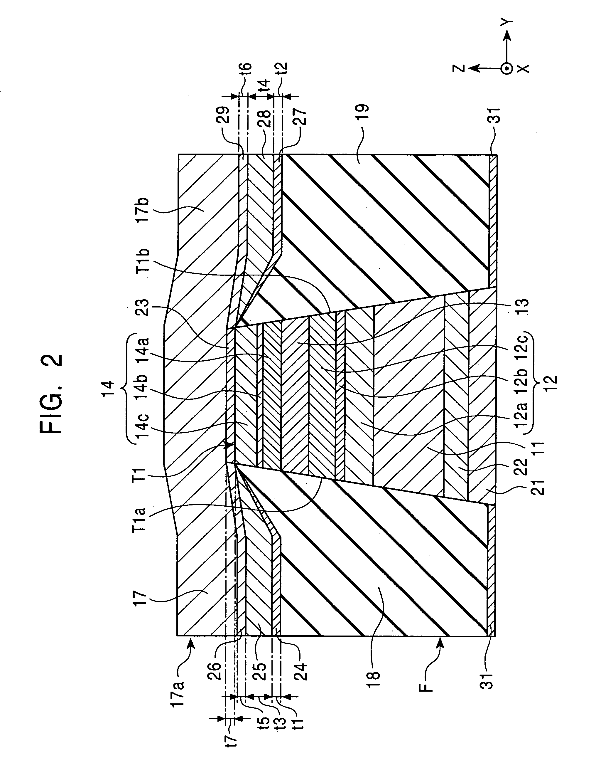
[0185]FIG. 4 is a longitudinal sectional view of a magnetic head according to the present invention taken along a plane perpendicular to the surface facing the recording medium.

[0186] The magnetic head shown in FIG. 4 is different from the magnetic head shown in FIG. 2 in that nonmagnetic intermediate layers 26 and 29 are laminated directly on magnetic domain control layers 18 and 19, and a magnetic flux guide layer 17 is formed on a nonmagnetic layer 23 and the nonmagnetic intermediate layers 26 and 29.

[0187] Even in the magnetic head comprising the magnetic domain control layers 18 and 19 each comprising an antiferromagnetic material such as the PtMn alloy, the X—Mn alloy or the Pt—Mn—X′ alloy, and the ferromagnetic layers 25 and 28 shown in FIGS. 1 and 2 are not formed, the presence of the nonmagnetic intermediate layers 26 and 29 permits the supply of an appropriately weak bias magnetic field to the magnetic flux guide layer 17.

[0188] Each of the nonmagnetic intermediate layer...

fourth embodiment

[0194]FIG. 5 is a perspective view schematically showing a magnetic head according to the present invention.

[0195] Like in the magnetic head shown in FIG. 1, in the magnetic head shown in FIG. 5, a multilayer film T1 comprising an antiferromagnetic layer 11, a pinned magnetic layer 12, a nonmagnetic material layer 13, and a free magnetic layer 14 is formed on a lower gap layer 16 laminated on a lower shield layer 15 to be disposed at a predetermined distance H1 from a surface F facing a recording medium in the height direction.

[0196] Also, a magnetic flux guide layer 17 is connected to the top of the free magnetic layer 14 of the multilayer film (magnetic detecting element) T1.

[0197] Furthermore, an upper shield layer 20 is laminated on the magnetic flux guide layer 17 with an upper gap layer (not shown in the drawing) provided therebetween and comprising a nonmagnetic material.

[0198] The magnetic head shown in FIG. 5 is different from the magnetic head shown in FIG. 1 in that lo...


PUM

PropertyMeasurementUnit
length H3aaaaaaaaaa
length H2aaaaaaaaaa
lengthaaaaaaaaaa

Abstract

The present invention provides a magnetic head including a magnetic flux guide layer for effectively inducing an external magnetic field in a free magnetic layer. A magnetic domain control layer is formed in a space below the magnetic flux guide layer and in front of a multilayer film near a surface facing a recording medium. Therefore, the shape of the magnetic flux guide layer can be made substantially flat to improve flux transmission efficiency. Also, the magnetization of the magnetic flux guide layer is controlled by laminating the magnetic flux guide layer on the magnetic domain control layer. Therefore, the magnetic domain control layer can be formed in a substantially flat thin film to stabilize a bias magnetic field to be supplied to the magnetic flux guide layer. Furthermore, the gap length of the magnetic head can be kept short.

Description

BACKGROUND OF THE INVENTION [0001] 1. Field of the Invention [0002] The present invention relates to a magnetic detecting element mainly used for a hard disk device and magnetic sensor, and a method of manufacturing the same. Particularly the present invention relates to a magnetic detecting element having excellent detectivity to a magnetic field, and a method of manufacturing the same. [0003] 2. Description of the Related Art [0004]FIG. 21 is a perspective view showing a conventional reproducing magnetic head. [0005] A magnetic detecting element S constituting the magnetic head shown in FIG. 21 comprises a multilayer film comprising a pinned magnetic layer 101, a nonmagnetic material layer 102, an a free magnetic layer 103. Each of the pinned magnetic layer 101 and the free magnetic layer 103 is made of a ferromagnetic material such as NiFe or the like, and the nonmagnetic material layer 102 is made of Cu or the like. [0006] The magnetization direction of the pinned magnetic layer...

Claims


Application Information

Patent Timeline
Patent Type & Authority Applications(United States)
IPC IPC(8): G11B5/39
CPCB82Y10/00B82Y25/00G11B5/3903Y10T29/49048G11B5/3932G11B2005/3996G11B5/3916
Inventor HASEGAWA, NAOYAUMETSU, EIJI
Owner TDK CORPARATION
Why Eureka
Try Eureka