Location-based addressing lighting and environmental control system, device and method

a technology of lighting and environmental control and location-based address, which is applied in the direction of programmatic control, audible advertising, instruments, etc., can solve the problems of system difficulty in maintenance, system scale not good, time-consuming process, etc., and achieve the effect of reducing traffic and efficient control of devices

Active Publication Date: 2011-02-15
THE WATT STOPPER
View PDF81 Cites 216 Cited by
  • Summary
  • Abstract
  • Description
  • Claims
  • Application Information

AI Technical Summary

Benefits of technology

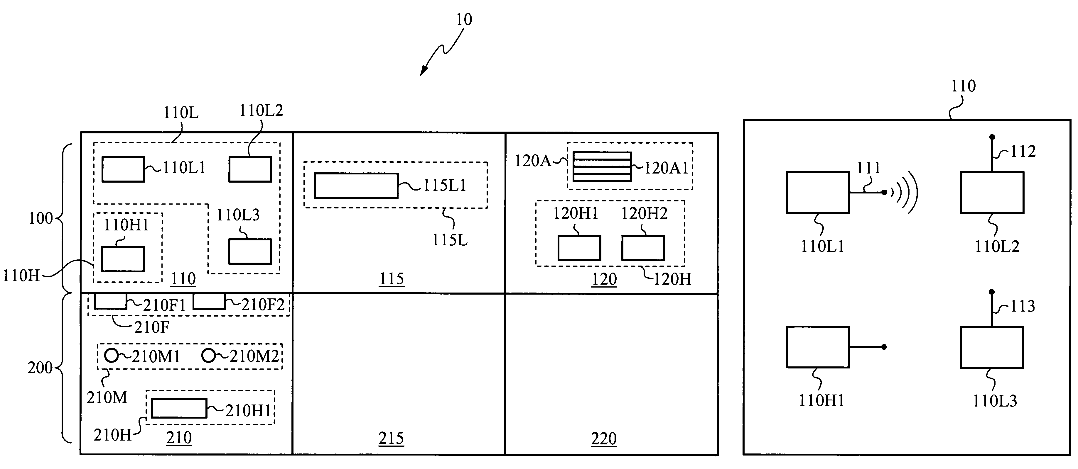
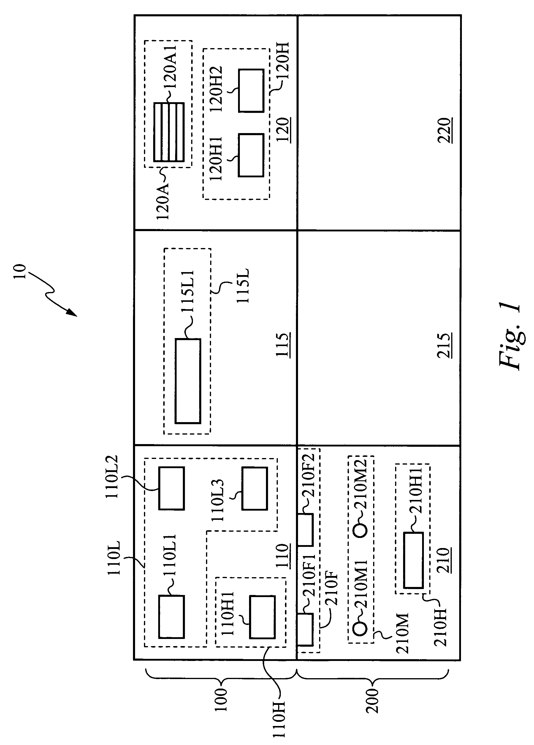
[0006]In accordance with the present invention, devices are commissioned into a set that preferably corresponds to a physical location, such as determined by a floor plan for a home, corporate building, or other structured physical environment. Electronic devices that are commissioned in accordance with the method of the present invention operate and inter-operate by messages directed to spatial locations rather than individual device addresses and thus require less bandwidth to implement the controls in contrast to two-way or “hand-shaking” methods of messaging typically used to communicate between devices.
[0008]A function code, for example, can instruct each target device to turn on or off or to adjust its settings. Because one control signal can control multiple devices, fewer control signals are needed to control these devices, reducing both the bandwidth used and the complexity of devices to be controlled.
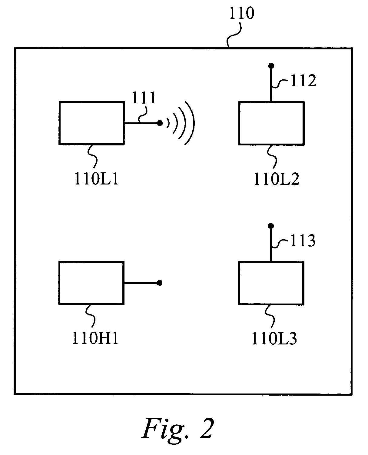
[0010]The system in accordance with the present invention efficiently controls devices using various means. For example, a transmitting device in the system transmits control signals as anonymous multicast signals, which do not use any handshaking protocols. The use of anonymous multicast signals reduces the number of control signals transmitted in accordance with the present invention, thus reducing traffic. Each receiving device is also programmed with a number of programmed functions. Each programmed function can be performed on the receiving device when the device is initially commissioned into a set, when the device receives a control signal containing a function code associated with the programmed function, or when an execution criterion is met, such as the occurrence of a programmed time. Thus, for example, by executing a programmed function on lighting units contained in a set, all of the lights in the set can be dimmed to a specific level at a specific time. As a fail-safe measure, the transmitting device can assure that the receiving devices receive the control signal by repeatedly transmitting the control signal multiple times within a given time window.
[0011]By organizing the LBAs in a hierarchical manner, devices can be more conveniently controlled. Sets corresponding to an LBA can, however, be configured in any number of ways. In one embodiment, a set contains a first set of devices located at a first location (such as a first area of a room) and a second set of devices located at a second location (such as a second area of a room). The first and second sets or groups of devices can be commissioned so that they have a LDs that are selectable or operable using a single LBA. Thus, these devices are addressable and can thus be controlled using a single control signal addressed with a single LBA. Sets can thus be configured and thus controlled in any number of ways to fit the application at hand.

Problems solved by technology

Second, these systems do not scale well.
When individually controlling multiple devices in a room, the control device must send commands to each device, a time-consuming process.
Third, these systems are difficult to maintain.
For these reasons, it is also difficult to automate or customize a system to control these devices.

Method used


Image

  • Location-based addressing lighting and environmental control system, device and method
  • Location-based addressing lighting and environmental control system, device and method
  • Location-based addressing lighting and environmental control system, device and method

Examples


Embodiment Construction

To facilitate the clarity of the ensuing description, words listed below have been ascribed the following meanings:

[0038]1) LOCATION—A position in a spatial environment, as commonly defined by the planner or user of that environment. Generally, a location is specified, for completeness, in a hierarchical manner that serves to uniquely define the position, for example, as the “main conference room on the third floor of the main building”. For most applications, a location corresponds to a place on, or section of, a building floor plan. For each location, there are often others that, by relation, are less or more specific than it, corresponding to higher or lower levels in the hierarchy; in the foregoing example, a less-specific location is the entire “third floor of the main building”, while a more specific example might be the “speaker's podium of the main conference room on the third floor of the main building”.

2) LOCATION DESCRIPTOR (“LD”)—An n-tuple that encodes a location, gener...


PUM


Abstract

Location-Based Addressing (LBA) is a method of controlling and commissioning networked lighting devices. The lighting devices communicate over a wireless network using radio frequency communication protocols. The lighting devices are commissioned or grouped based on their respective locations in a building floor plan or a building architecture. The lighting devices are commissioned to respond to radio frequency communications that correspond to their respective locations. This imposed location-based architecture reduces the amount of transmitted data required to control the lighting devices and, thus, reduces the radio bandwidth required to control the lighting devices. In other words, controlling devices “multicast” instructions and controlled devices “listen” for instructions and act only upon instructions that correspond to their respective location. Hand shaking or two-way communication between the controlling devices and the controlled devices is not required.

Description

RELATED APPLICATIONS[0001]This application claims priority under 35 U.S.C. §119(e) from the co-pending U.S. provisional patent application Ser. No. 60 / 500,640, filed on Sep. 5, 2003, and titled “LOCATION-BASED ADDRESSING LIGHTING AND ENVIRONMENTAL CONTROL SYSTEM, DEVICE AND METHOD.” The provisional patent application Ser. No. 60 / 500,640, filed on Sep. 5, 2003, and titled “LOCATION-BASED ADDRESSING LIGHTING AND ENVIRONMENTAL CONTROL SYSTEM, DEVICE AND METHOD” is hereby incorporated by reference.FIELD OF THE INVENTION[0002]This invention relates to the field of lighting and environmental control systems, devices and methods. More particularly, this invention relates to systems, devices, and methods that use addressing to control lighting and environmental control systems.BACKGROUND OF THE INVENTION[0003]Residential home owners often wish to remotely control electrical components in their homes. A home owner may, for example, wish to control the electrical components from a control dev...

Claims


Application Information

Patent Timeline
Patent Type & Authority Patents(United States)
IPC IPC(8): G06K19/00G09F25/00
CPCH04L12/2818H04L29/12254H04L61/2038G08B15/002H05B37/0272H04L61/609H04L2012/285H05B47/19H04L61/5038H04L2101/69
Inventor BILLIG, RICHARD R.DEBERNARD, ALEXANDREDEBEVER, BERTRAND
Owner THE WATT STOPPER
Why Eureka
Try Eureka