Memory command delay balancing in a daisy-chained memory topology

a topology and memory command technology, applied in memory systems, instruments, sustainable buildings, etc., can solve the problems of overall delay in data transfer operations, inconvenient parallel bus configuration, and limited speed with which signaling can be carried out on the bus, so as to efficiently control the power profile of all the dram devices

Inactive Publication Date: 2006-02-23
ROUND ROCK RES LLC
View PDF9 Cites 192 Cited by
  • Summary
  • Abstract
  • Description
  • Claims
  • Application Information

AI Technical Summary

Benefits of technology

[0023] The present disclosure describes a methodology for a daisy-chained memory topology wherein, in addition to the prediction of the timing of receipt of a response from a memory module (DIMM), the memory controller can effectively predict when a command sent by it will be executed by the addressee DIMM. By programming DIMM-specific command delay in the DIMM's command delay unit, the command delay balancing methodology according to the present disclosure “normalizes” or “synchronizes” the execution of the command signal across all DIMMs in the memory channel. With such ability to predict command execution timing, the memory controller can efficiently control power profile of all the DRAM devices (or memory modules) on a daisy-chained memory channel. A separate DIMM-specific response delay unit in the DIMM may also be programmed to provide DIMM-specific delay compensation in the response path, further allowing the memory controller to accurately ascertain the timing of receipt of a response thereat to an earlier command sent thereby, and, hence, to better manage or plan (time-wise) further processing of the response.

Problems solved by technology

While such an arrangement may be easier to implement and may provide a “wider” memory bus, a penalty to be paid is the limited speed with which signaling can be carried out on the bus 30.
Further, in the parallel bus configuration, any delay encountered in the slowest DIMM governs the overall delay in data transfer operations.
To increase the signaling speed of memory data transfer operations in the GHz region to avail of the processing power of modern faster memory chips and controllers, the parallel bus configuration may not be suitable.
Thus, one disadvantage of the serial daisy-chaining is that a defect or malfunction at one of the memory modules may prevent further “downstream” propagation of the command from the memory controller 33.
For example, some DRAM operations, such as a “Refresh” command, may consume a lot of power.

Method used


Image

  • Memory command delay balancing in a daisy-chained memory topology
  • Memory command delay balancing in a daisy-chained memory topology
  • Memory command delay balancing in a daisy-chained memory topology

Examples


Embodiment Construction

[0030] Reference will now be made in detail to some embodiments of the present disclosure, examples of which are illustrated in the accompanying figures. It is to be understood that the figures and descriptions of the present disclosure included herein illustrate and describe elements that are of particular relevance to the present disclosure, while eliminating, for the sake of clarity, other elements found in typical data storage or memory systems. It is noted at the outset that the terms “connected”, “connecting,”“electrically connected,” etc., are used interchangeably herein to generally refer to the condition of being electrically connected.

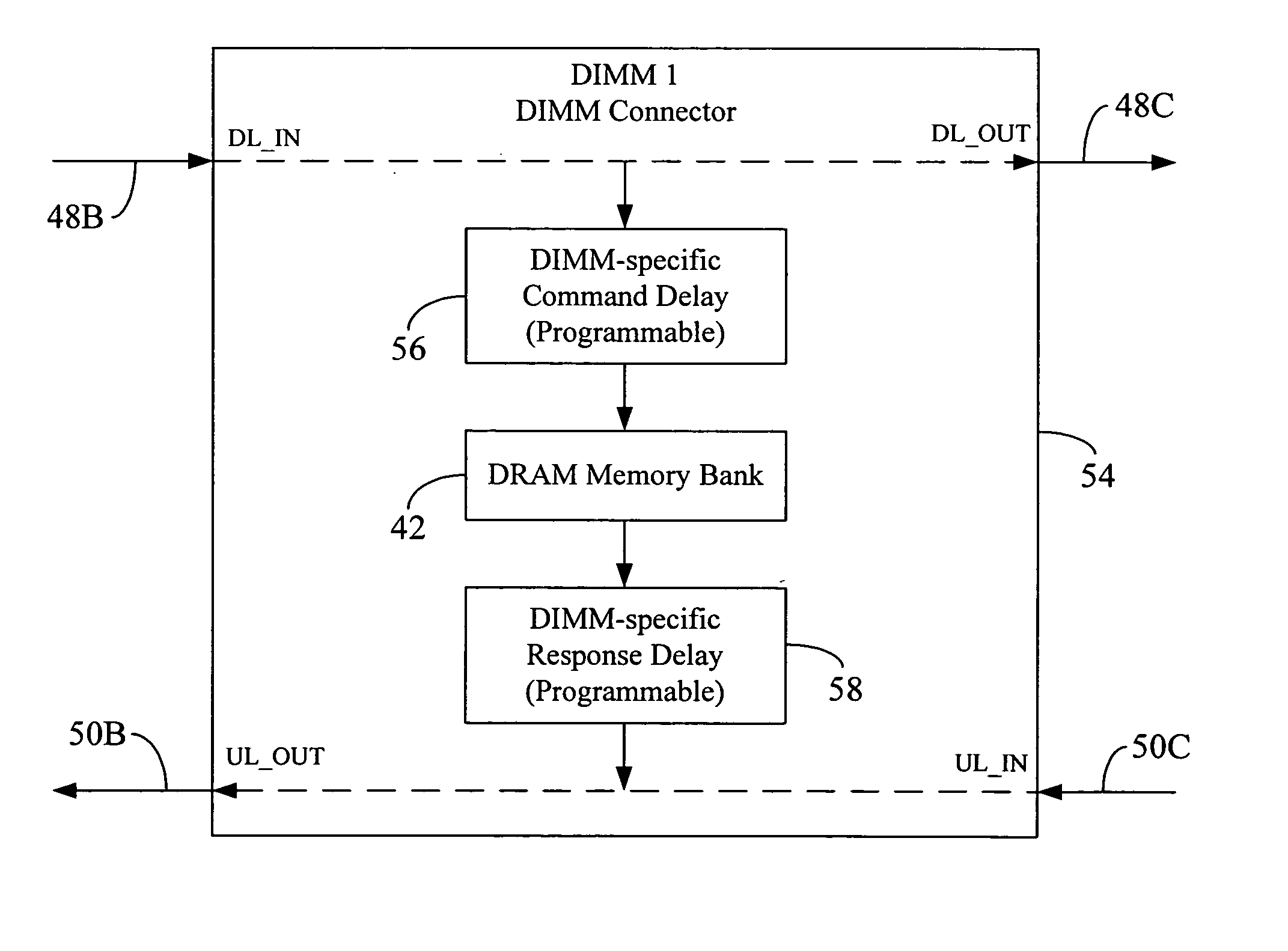
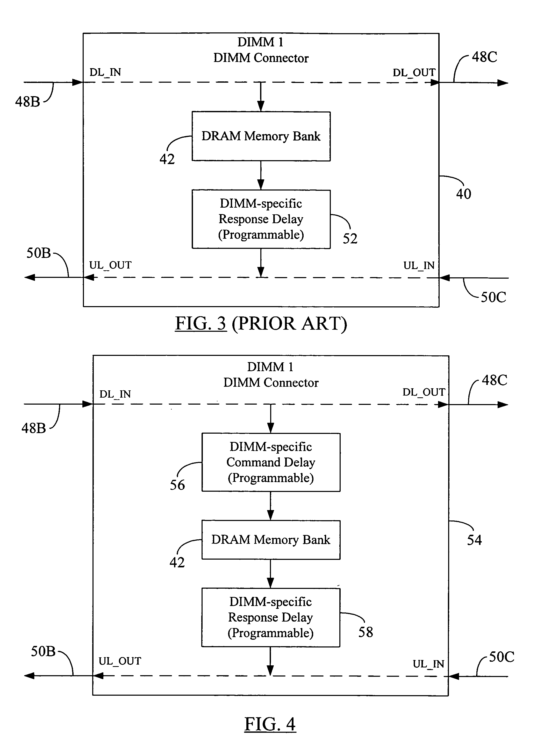
[0031]FIG. 4 depicts a command delay balancing methodology according to one embodiment of the present disclosure. For ease of illustration, only one memory module (DIMM) 54 with a DIMM-specific programmable command delay unit 56 is illustrated. The DIMM 54 may be a modified version of the DIMM 40 in FIG. 3 and, hence, it is also designated a...


PUM


Abstract

A methodology for a daisy-chained memory topology wherein, in addition to the prediction of the timing of receipt of a response from a memory module (DIMM), the memory controller can effectively predict when a command sent by it will be executed by the addressee DIMM. By programming DIMM-specific command delay in the DIMM's command delay unit, the command delay balancing methodology according to the present disclosure “normalizes” or “synchronizes” the execution of the command signal across all DIMMs in the memory channel. With such ability to predict command execution timing, the memory controller can efficiently control power profile of all the DRAM devices (or memory modules) on a daisy-chained memory channel. A separate DIMM-specific response delay unit in the DIMM may also be programmed to provide DIMM-specific delay compensation in the response path, further allowing the memory controller to accurately ascertain the timing of receipt of a response thereat, and, hence, to better manage further processing of the response.

Description

BACKGROUND [0001] 1. Field of the Disclosure [0002] The present disclosure generally relates to memory systems and, more particularly, to command delay balancing in daisy-chained memory devices. [0003] 2. Brief Description of Related Art [0004] Memory devices are widely used in many electronic products and computers to store data. A memory device is a semiconductor electronic device that includes a number of memory chips, each chip storing a portion of the total data. The chips themselves contain a large number of memory cells, with each cell storing a bit of data. The memory chips may be part of a DIMM (dual in-line memory module) or a PCB (printed circuit board) containing many such memory chips. In the discussion hereinbelow, the terms “memory device”, “memory module” and “DIMM” are used synonymously. A processor or memory controller may communicate with the memory devices in the system to perform memory read / write and testing operations. FIG. 1 illustrates a prior art arrangemen...

Claims


Application Information

Patent Timeline
Patent Type & Authority Applications(United States)
IPC IPC(8): G06F13/00
CPCG06F13/4243Y02B60/1228Y02B60/1235G06F3/0629G06F3/0611G06F3/0671G11C7/22Y02D10/00G06F12/00G06F13/14G06F13/16
Inventor LARSON, DOUGLAS ALAN
Owner ROUND ROCK RES LLC
Why Eureka
Try Eureka