Generation of high dynamic range images from low dynamic range images

a high dynamic range and image technology, applied in the field of high dynamic range image generation from low dynamic range image, can solve the problems of insufficient headroom and accuracy to convey traditional video formats, annoying quantization and clipping artifacts, and the dynamic range of reproduced images has tended to be substantially reduced in relation to normal vision, so as to improve the prediction of an hdr image, improve the encoding of hdr images, and reduce residual signals

Inactive Publication Date: 2013-05-02
KONINKLIJKE PHILIPS ELECTRONICS NV
View PDF12 Cites 36 Cited by
  • Summary
  • Abstract
  • Description
  • Claims
  • Application Information

AI Technical Summary

Benefits of technology

[0019]The invention may provide improved encoding of HDR images. In particular, improved prediction of an HDR image from an LDR image may be achieved allowing a reduced residual signal and thus more efficient encoding. A data rate of the enhancement layer, and thus of the combined signal, may be achieved.
[0020]The approach may allow prediction to be based on an improved and/or automatic adaptation to the specific relationship between HDR and LDR images. For example, the approach may automatically adapt to reflect the application of different ...

Problems solved by technology

However, conventionally, the dynamic range of reproduced images has tended to be substantially reduced in relation to normal vision.
When traditionally encoded 8-bit signals are displayed on such displays, annoying quantization and clipping artifacts may appear.
Moreover, traditional video formats offer insufficient headroom and accuracy to convey the rich information contained in new HDR imagery.
However, this would result in a high data rate.
However, prediction of HDR from LDR data tends to be difficult and relatively inaccurate.
Indeed, the relationship between corresponding LDR and HDR tends to be very complex and may often vary strongly between different parts of the image.
Consequently, prediction of HDR images from LDR i...

Method used


Image

  • Generation of high dynamic range images from low dynamic range images
  • Generation of high dynamic range images from low dynamic range images
  • Generation of high dynamic range images from low dynamic range images

Examples


Embodiment Construction

[0095]The following description focuses on embodiments of the invention applicable to encoding and decoding of corresponding low dynamic range and high dynamic range images of video sequences. However, it will be appreciated that the invention is not limited to this application and that the described principles may be applied in many other scenarios and may e.g. be applied to enhance or modify dynamic ranges of a large variety of images.

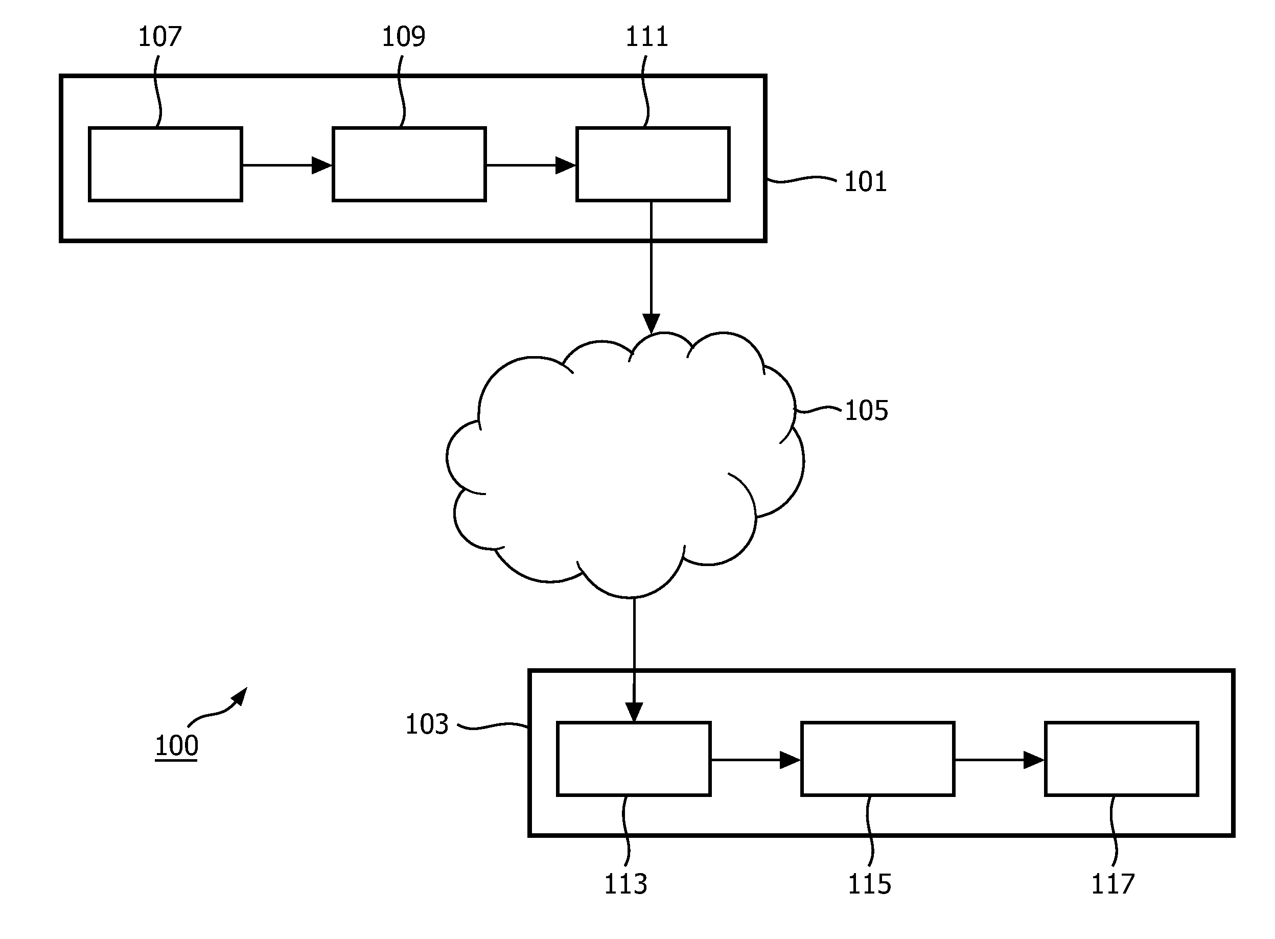
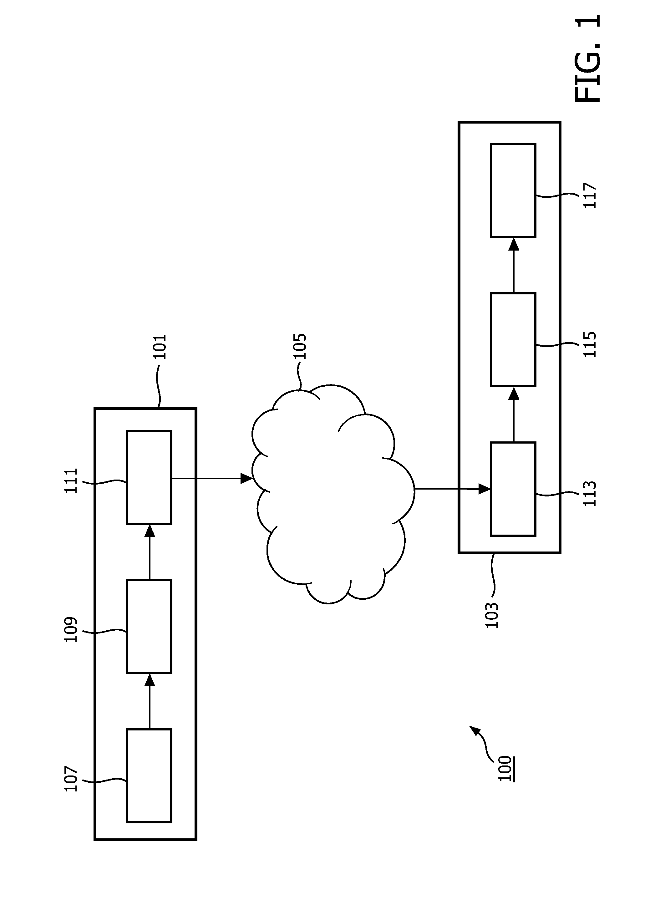
[0096]FIG. 1 illustrates a transmission system 100 for communication of a video signal in accordance with some embodiments of the invention. The transmission system 100 comprises a transmitter 101 which is coupled to a receiver 103 through a network 105 which specifically may be the Internet or e.g. a broadcast system such as a digital television broadcast system.

[0097]In the specific example, the receiver 103 is a signal player device but it will be appreciated that in other embodiments the receiver may be used in other applications and for other pu...


PUM


Abstract

An approach is provided for generating a high dynamic range image from a low dynamic range image. The generation is performed using a mapping relating input data in the form of input sets of image spatial positions and a combination of color coordinates of low dynamic range pixel values associated with the image spatial positions to output data in the form of high dynamic range pixel values. The mapping is generated from a reference low dynamic range image and a corresponding reference high dynamic range image. Thus, a mapping from the low dynamic range image to a high dynamic range image is generated on the basis of corresponding reference images. The approach may be used for prediction of high dynamic range images from low dynamic range images in an encoder and decoder. A residual image may be generated and used to provide improved high dynamic range image quality.

Description

FIELD OF THE INVENTION[0001]The invention relates to generation of high dynamic range images from low dynamic range images and in particular, but not exclusively, to generation of high dynamic range video sequences from low dynamic range video sequences.BACKGROUND OF THE INVENTION[0002]Digital encoding of various source signals has become increasingly important over the last decades as digital signal representation and communication increasingly has replaced analogue representation and communication. Continuous research and development is ongoing in how to improve the quality that can be obtained from encoded images and video sequences while at the same time keeping the data rate to acceptable levels.[0003]An important factor for perceived image quality is the dynamic range that can be reproduced when an image is displayed. However, conventionally, the dynamic range of reproduced images has tended to be substantially reduced in relation to normal vision. Indeed, luminance levels enc...

Claims


Application Information

Patent Timeline
IPC IPC(8): H04N7/26H04N19/593
CPCG06T9/004H04N19/597H04N19/105H04N19/30H04N19/187H04N19/103H04N19/14H04N19/154H04N19/184H04N19/593H04N19/87
Inventor MUIJS, REMCO THEODORUS JOHANNESBRULS, WILHELMUS HENDRIKUS ALFONSUS
Owner KONINKLIJKE PHILIPS ELECTRONICS NV
Why Eureka
Try Eureka