Control device of vehicle

a control device and vehicle technology, applied in the direction of propulsion parts, batteries/cells, transportation and packaging, etc., can solve the problems of engine fluctuation, decrease in the commercial value of the vehicle from a so-called noise vibration (nv) viewpoint, and increase the cost of the vehicl

Active Publication Date: 2021-09-02
HONDA MOTOR CO LTD
View PDF8 Cites 2 Cited by
  • Summary
  • Abstract
  • Description
  • Claims
  • Application Information

AI Technical Summary

Benefits of technology

[0006]If the difference in reduction ratio between the power transmission paths is reduced, the fluctuation of the rotational speed of the internal combustion engine that occurs when the power transmission path is switched can be reduced.
[0008]The present disclosure provides a control device for a vehicle that can suppress a fluctuation in a rotational speed of an internal combustion engine when switching a power transmission path to be used with a simple configuration.
[0010]According to the present disclosure, at the time of the transition from the first traveling mode using the first power transmission path having the first reduction ratio to the second traveling mode using the second power transmission path having the second reduction ratio via the third traveling mode, in which the vehicle can travel by the power of the electric motor, the rotational speed of the internal combustion engine in the third traveling mode is controlled to be the third rotational speed that is between the first rotational speed at the time of transition from the first traveling mode to the third traveling mode and the second rotational speed at the time of transition from the third traveling mode to the second traveling mode, so that fluctuation in the rotational speed of the internal combustion engine when switching a power transmission path to be used can be suppressed with a simple configuration.

Problems solved by technology

However, when the above method is adopted, depending on a difference between the reduction ratio of the power transmission path before switching and the reduction ratio of the power transmission path after the switching, there is a concern that a rotational speed of the internal combustion engine fluctuates greatly when the power transmission path is switched, which may lead to a decrease in a marketability of the vehicle from a viewpoint of vibration and noise, that is, a decrease in commercial value of the vehicle from a so-called noise vibration (NV) viewpoint.
However, in such a case, when the vehicle is to be efficiently driven by the power of the internal combustion engine in a wide range of a traveling state, a large number of power transmission paths are required, which leads to an increase in manufacturing cost and weight of the vehicle.

Method used


Image

  • Control device of vehicle
  • Control device of vehicle
  • Control device of vehicle

Examples


Embodiment Construction

[0019]Hereinafter, an embodiment of a control device of a vehicle according to the present disclosure will be described in detail with reference to the drawings.

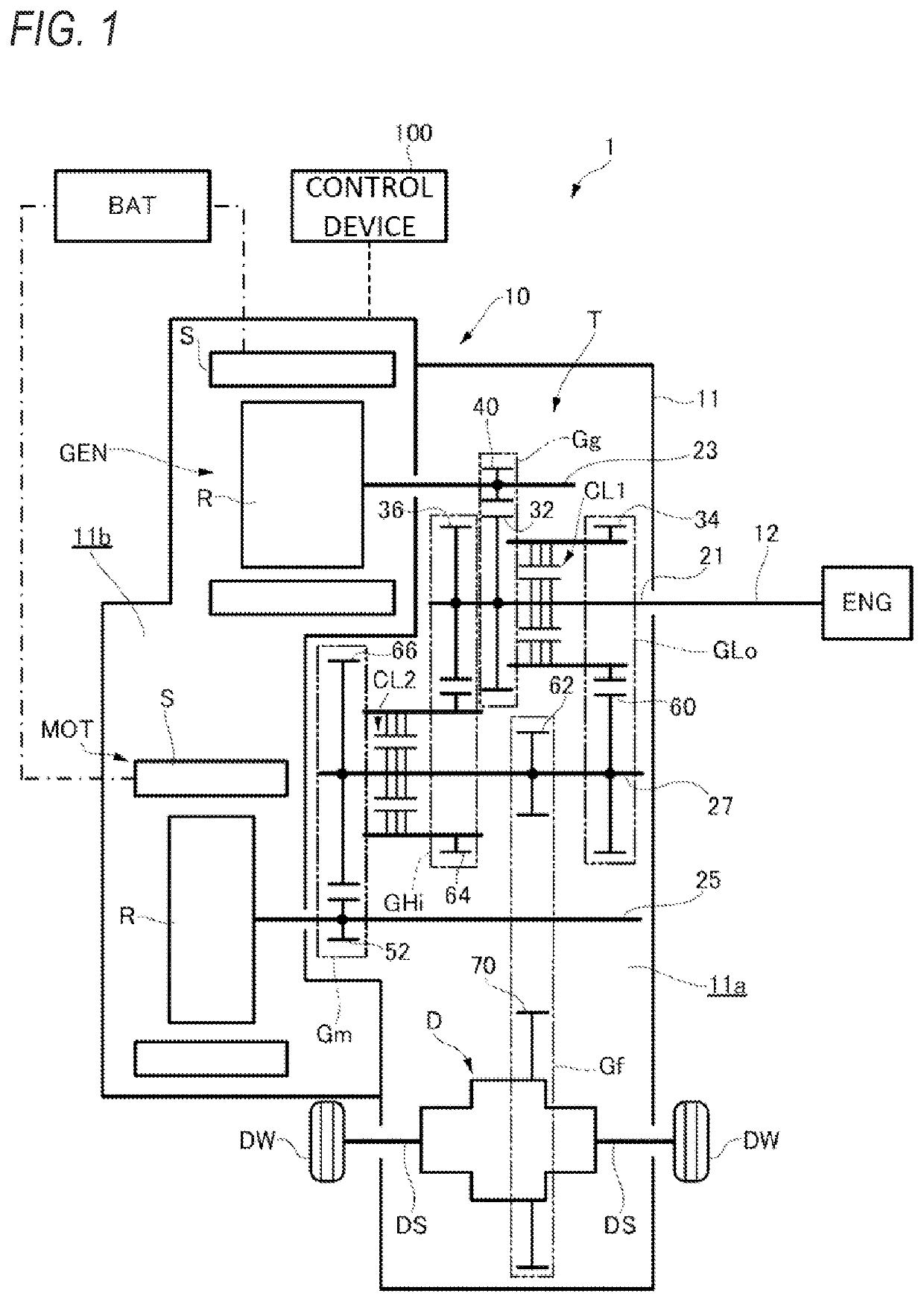
[0020]First, a vehicle including the control device of a vehicle according to the present embodiment will be described with reference to FIG. 1. As illustrated in FIG. 1, a vehicle 1 of the present embodiment includes a driving device 10 that outputs a driving force of the vehicle 1, and a control device 100 that controls the entire vehicle 1 including the driving device 10.

Driving Device

[0021]As illustrated in FIG. 1, the driving device 10 includes an engine ENG, a generator GEN, a motor MOT, a transmission T, and a case 11 that accommodates the generator GEN, the motor MOT, and the transmission T. The motor MOT and the generator GEN are connected to a battery BAT included in the vehicle 1, which enables electric power supply from the battery BAT and energy regeneration to the battery BAT.

Transmission

[0022]The case 11 is pr...


PUM


Abstract

A traveling mode setting unit configured to cause a shift to shift to a second traveling mode via a third traveling mode based on a traveling state of the vehicle traveling in the first traveling mode. The internal combustion engine control unit includes a derivation unit configured to derive a second rotational speed of the internal combustion engine at the time of transition from the third traveling mode to the second traveling mode based on a first rotational speed of the internal combustion engine at the time of transition from the first traveling mode to the third traveling mode, the traveling state of the vehicle and the second reduction ratio, and the internal combustion engine control unit is configured to control a third rotational speed of the internal combustion engine in the third traveling mode to be a value between the first rotational speed and the second rotational speed.

Description

CROSS-REFERENCE TO RELATED APPLICATIONS[0001]This application is based on and claims priority under 35 USC 119 from Japanese Patent Application No. 2020-033433 filed on Feb. 28, 2020.TECHNICAL FIELD[0002]The present disclosure relates to a control device of a vehicle.BACKGROUND ART[0003]In recent years, a hybrid electrical vehicle has a plurality of traveling modes including a hybrid traveling mode, in which a generator generates electric power based on power of an engine in a state where a clutch is disengaged and an electric motor outputs power at least based on the electric power supplied by the generator to drive a driving wheel, and an engine traveling mode, in which the driving wheel is driven by at least power output by the engine in a state where the clutch is engaged (for example, see WO-A-2019-003443).[0004]As a method of efficiently driving a vehicle by power of an internal combustion engine, there may be a method in which a plurality of power transmission paths each havi...

Claims


Application Information

Patent Timeline
Patent Type & Authority Applications(United States)
IPC IPC(8): B60W20/15B60W30/182B60W10/06B60W10/08B60W10/10
CPCB60W20/15B60W30/182B60W10/02B60W10/08B60W10/10B60W10/06B60L50/61B60W20/20B60W20/17B60W2710/0644B60W20/11B60W20/30B60K6/442B60K6/387B60K2006/4808B60K6/547B60W2710/0661Y02T10/62Y02T10/70B60W20/00
Inventor INOUE, MAMIKOHATSUDA, JUNPEISAKAGUCHI, YUSUKE
Owner HONDA MOTOR CO LTD
Why Eureka
Try Eureka