Ultrasound flaw detector, ultrasound flaw detection method, and program

Pending Publication Date: 2022-01-06
KONICA MINOLTA INC
View PDF0 Cites 0 Cited by
  • Summary
  • Abstract
  • Description
  • Claims
  • Application Information

AI Technical Summary

Benefits of technology

The objective of this patent is to improve the quality of a reception signal when testing an object in a liquid.

Problems solved by technology

On the other hand, these ultrasound probes are unsuitable for testing a test object having a complicated shape, such as an object formed by welding members of different shapes, an object formed by integrally molding a composite material such as carbon fiber reinforced plastics (CFRP) or light metal by casting (casting process), etc., because it is impossible to bring them into direct and close contact with such test object.
However, in the method in which the test object is immersed in the liquid, the quality of a reception signal is not sufficiently improved depending on the relationship between the surface of the test object and the irradiation direction of an ultrasound beam from the ultrasound probe.
Particularly when the ultrasound beam is emitted in a direction perpendicular to the surface of the test object, the quality of the reception signal may not be sufficient.

Method used


Image

  • Ultrasound flaw detector, ultrasound flaw detection method, and program
  • Ultrasound flaw detector, ultrasound flaw detection method, and program
  • Ultrasound flaw detector, ultrasound flaw detection method, and program

Examples


embodiment

[0029]Hereinafter, an ultrasound flaw detector 100 according to the embodiment will be described with reference to the drawings.

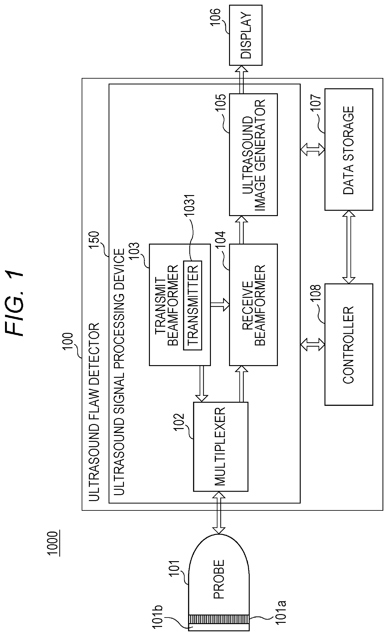
[0030]FIG. 1 is a functional block diagram showing a configuration of the ultrasound flaw detection system 1000 according to the embodiment. As shown in FIG. 1, the ultrasound flaw detection system 1000 includes: a probe 101 having a plurality of transducers 101a that transmits ultrasound waves to a test object and receives reflection of the ultrasound waves; the ultrasound flaw detector 100 that causes the probe 101 to transmit and receive ultrasound waves and generates an ultrasound image on the basis of an output signal from the probe 101; and a display 106 that displays the ultrasound image on a screen. Each of the probe 101 and the display 106 is connectable to the ultrasound flaw detector 100. FIG. 1 shows a state in which the probe 101 and the display 106 are connected to the ultrasound flaw detector 100. Note that the probe 101 and the display 106 m...


PUM


Abstract

An ultrasound flaw detector includes: an ultrasound probe that is provided with a plurality of transducers and that is held so that a direction in which the transducers are arrayed is parallel to a surface of the test object in a state where the plurality of transducers is located in the liquid; a hardware processor that, using the plurality of transducers, transmits an ultrasound beam in a first direction with a predetermined angle with respect to a normal direction of the surface of the test object and receives a reflected ultrasound wave reflected by the test object; and an ultrasound signal processor that specifies a flaw of the test object on the basis of a reception signal that has been generated by the hardware processor on the basis of the reflected ultrasound wave.

Description

[0001]The entire disclosure of Japanese patent Application No. 2020-115544, filed on Jul. 3, 2020, is incorporated herein by reference in its entirety.BACKGROUNDTechnological Field[0002]The present disclosure relates to an ultrasound flaw detector and an ultrasound flaw detection method, and more particularly to a method of treating reflected ultrasound waves.Description of the Related Art[0003]An ultrasound flaw detection method is used as a non-destructive inspection of structures. It is widely used particularly for the purpose of detecting defects around a welded part of a welded structure or defects on the surface or inside of an integrally molded structure, because it does not need a large-scale accessory device such as shielding as compared with radiographic testing.[0004]When inspection is carried out for a test object having a fixed shape, an ultrasound probe (probe) having a shape capable of being in close contact with the test object is used (for example, see JP 2014-23204...

Claims


Application Information

Patent Timeline
IPC IPC(8): G01N29/07G01N29/28G01N29/24G01N29/22
CPCG01N29/07G01N29/28G01N29/2437G01N2291/044G01N2291/106G01N2291/011G01N2291/023G01N29/223G01N29/043G01N29/225G01N29/265G01N29/221
InventorWATANABE, YASUHITO
OwnerKONICA MINOLTA INC