Apparatus for use with non-lethal, electrical discharge weapons

a technology of electrical discharge and apparatus, applied in the direction of biochemical apparatus and processes, firearms, small arms, etc., can solve the problems of only having weapons, compromising weapon effectiveness, and losing distance between the opposing contacts of long-range weapons, so as to add a long-range capability to the weapon

Inactive Publication Date: 2000-04-25
ELECTRONICS MEDICAL RES LAB
View PDF11 Cites 42 Cited by
  • Summary
  • Abstract
  • Description
  • Claims
  • Application Information

AI Technical Summary

Benefits of technology

It is therefore a principal object of the present invention to provide an apparatus for addition to a close proximity electrical discharge weapon to add a long range capability to the weapon.
It is another object of the invention to provide an after-market device which permits users of close proximity electrical discharge weapons to add a long range wire-tethered dart system to their weapons and to make the close proximity function more effective.
It is still another object of the invention to provide a method for modifying a close proximity electrical discharge weapon to give the weapon a long range capability and to increase the spread of the contact probes in the close proximity mode of operation.
It is still another object of the invention to increase the spread between the contacts of a close proximity electrical discharge weapon while separating the weapons breakdown electrodes and, thereby, increasing the weapon's target penetrating voltage.

Problems solved by technology

With close proximity perpetrators, a loss of distance between the long range weapon's opposed contacts at the target is observed to jeopardize weapon effectiveness.
However, these weapons are only available if purchased with this dual function capability to start with.
As with the other dual function weapons described above, it does nothing to improve the effectiveness of the close proximity function.
Moreover, ammunition cannot be reloaded into the attachment.

Method used


Image

  • Apparatus for use with non-lethal, electrical discharge weapons
  • Apparatus for use with non-lethal, electrical discharge weapons
  • Apparatus for use with non-lethal, electrical discharge weapons

Examples


Embodiment Construction

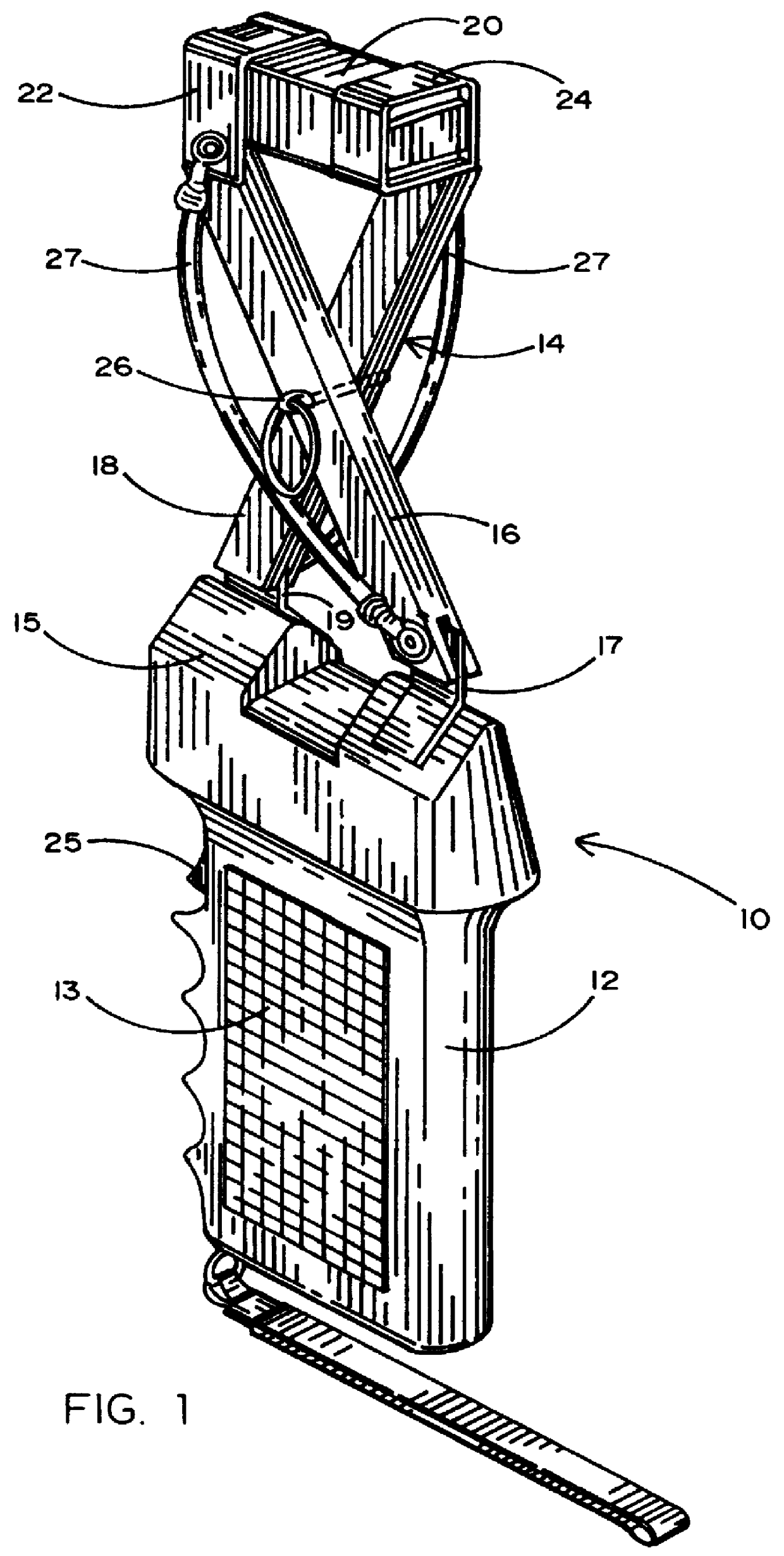
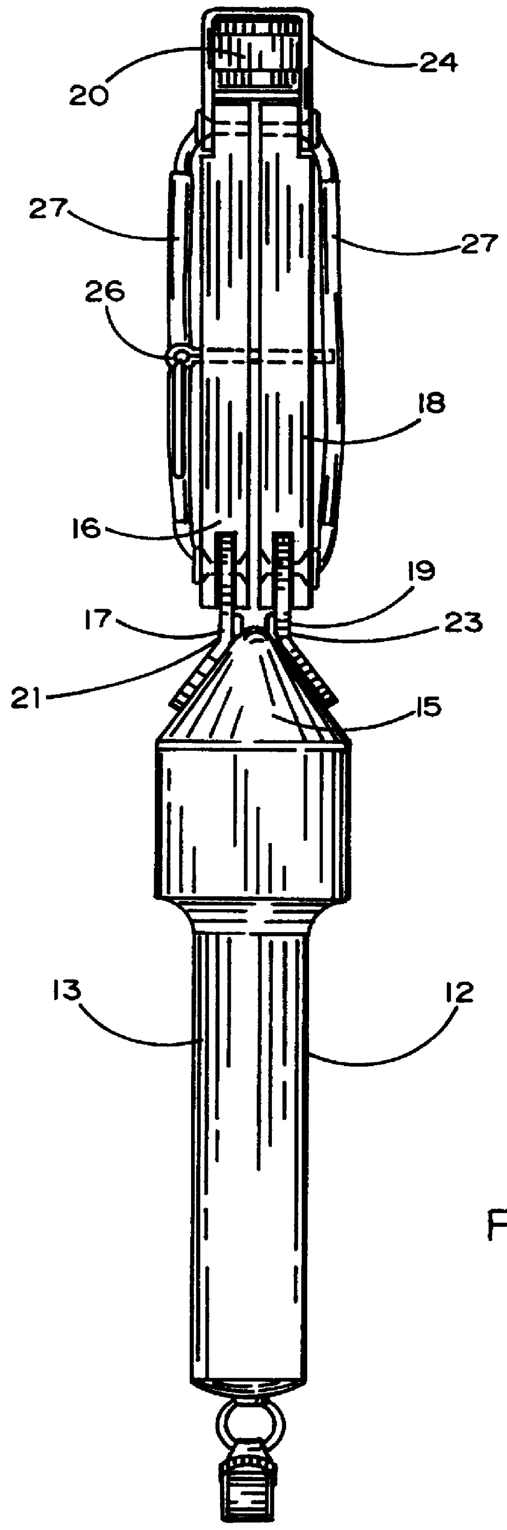
Referring to the accompanying drawings, it will be seen that an improved, non-lethal, electrical discharge weapon 10 comprises a conventional hand held close proximity device 12 to which, by virtue of the present invention, there has been added a dart launcher assembly 14. The device 12 has a handle portion 13 and a head portion 15, the latter having a pair of electrodes 21 and 23. The launcher assembly 14 is attached to the head portion 15 by a pair of connection members 17 and 19, which make contact with electrodes 21 and 23, respectively.

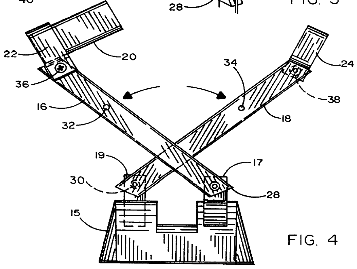
The launcher assembly comprises a pair of extender arms 16 and 18. The arms are attached to the connection members 17 and 19 for limited articulation relative thereto and have heavy gauge wires 27 running through them. Arms 16 and 18 extend upwardly (as seen in FIG. 1) from head portion 15 in a crossing diagonal fashion so that they overlap at their approximate mid-point. There at the overlap, the two arms are joined by a stabilizer 26. Arms 16 a...


PUM

PropertyMeasurementUnit
mechanicalaaaaaaaaaa
electricalaaaaaaaaaa
acute angleaaaaaaaaaa

Abstract

An addition device which permits a user of a close proximity electrical discharge weapon to modify his or her weapon by providing an improved short range capability as well as a long range capability which can be added as an after-market improvement. The invention is an apparatus designed to be mechanically and electrically attached to the device and provides a wire-tethered dart cartridge which extends above the weapon and gives the user the additional capability of contacting long range targets. The apparatus permits easy and convenient replacement of spent cartridges as well as easy and convenient connection to the close proximity device. The apparatus also improves short range performance by widening the separation of contact electrodes and by increasing the penetration voltage to increase effectiveness.

Description

1. Field of the InventionThe present invention relates generally to the field of non-lethal, electrical discharge weapons such as TASER.RTM. devices and more specifically to a device which is designed to be added as an accessory to such weapons of a close proximity type to provide a long range capability and improve short range effectiveness.2. Prior ArtElectrical discharge weapons have become fairly commonplace in recent years. Numerous U.S. patents have issued for invention of such weapons and for their further improvement. U.S. Pat. No. 3,523,538 issued to Shimzu on Aug. 11, 1970; U.S. Pat. No. 3,803,463 issued to Cover on Apr. 9, 1974; U.S. Pat. No. 4,253,132 issued to Cover on Feb. 24, 1981; U.S. Pat. No. 5,473,501 issued to Claypool on Dec. 5, 1995; U.S. Pat. No. 5,654,867 issued to Murray on Aug. 5, 1997; and U.S. Pat. No. 5,698,815 issued to Ragner on Dec. 16, 1997. They provide an effective but non-lethal form of self-defense which may be legally carried on one's person for...

Claims


Application Information

Patent Timeline
Patent Type & Authority Patents(United States)
IPC IPC(8): A22B3/06A22B3/00C12N15/49
CPCA22B3/06F41H13/0025F41H13/0018
Inventor MCNULTY, JR., JAMES F.
Owner ELECTRONICS MEDICAL RES LAB
Why Eureka
Try Eureka