Dual-fuel valve

a dual-fuel valve and valve body technology, applied in the direction of machines/engines, mechanical equipment, transportation and packaging, etc., can solve the problems of complex engine fueling matter, yet meeting emission standards, and configuring the valv

Inactive Publication Date: 2000-05-30
GENERAC POWER SYSTEMS
View PDF14 Cites 40 Cited by
  • Summary
  • Abstract
  • Description
  • Claims
  • Application Information

AI Technical Summary

Benefits of technology

A highly preferred embodiment of the valve includes structure which prevents the adjustment member from being moved to a position at which the relevant emission standard would be exceeded. To that end, a stop mechanism is mounted with respect to the body and limits movement of the adjustment member between a first position at which the orifice area is a smaller or first area (which is greater than zero, i.e., the

Problems solved by technology

But the matter of engine fueling while yet meeting emission standards becomes more complex when an engine is to be fueled with either of two fuels

Method used


Image

  • Dual-fuel valve
  • Dual-fuel valve
  • Dual-fuel valve

Examples


Embodiment Construction

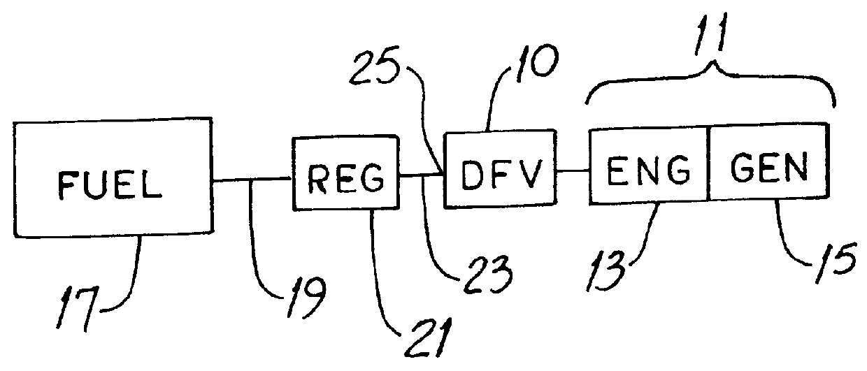
Before describing the new dual-fuel valve 10 in detail, it will be helpful to have an understanding of an exemplary way in which such valve 10 is used. Referring to FIGS. 1 and 2, a standby power unit 11 has an internal combustion engine 13 coupled to a portable electrical generator 15. A source of fuel, e.g., a tank 17 containing natural gas or LPG, is mounted near the unit 11 and a fuel line 19 connects the tank 17 to a pressure regulator 21. Another line 23 connects the pressure regulator 21 to the valve inlet port 25.

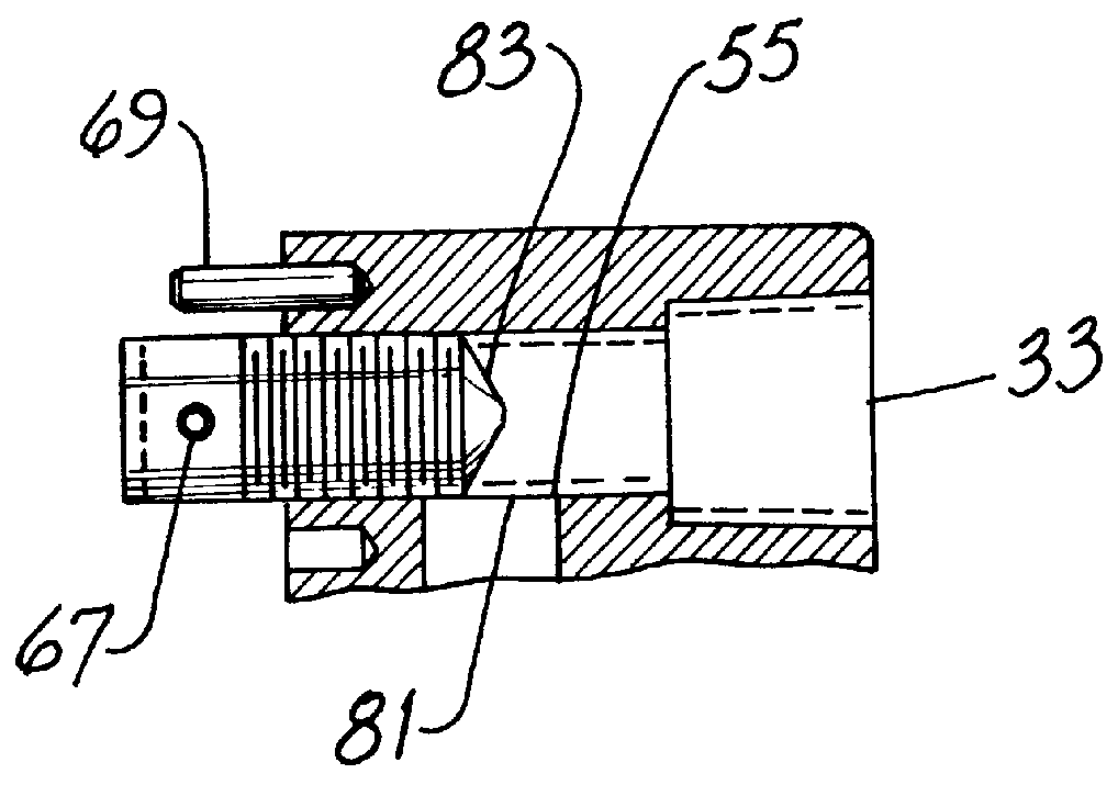
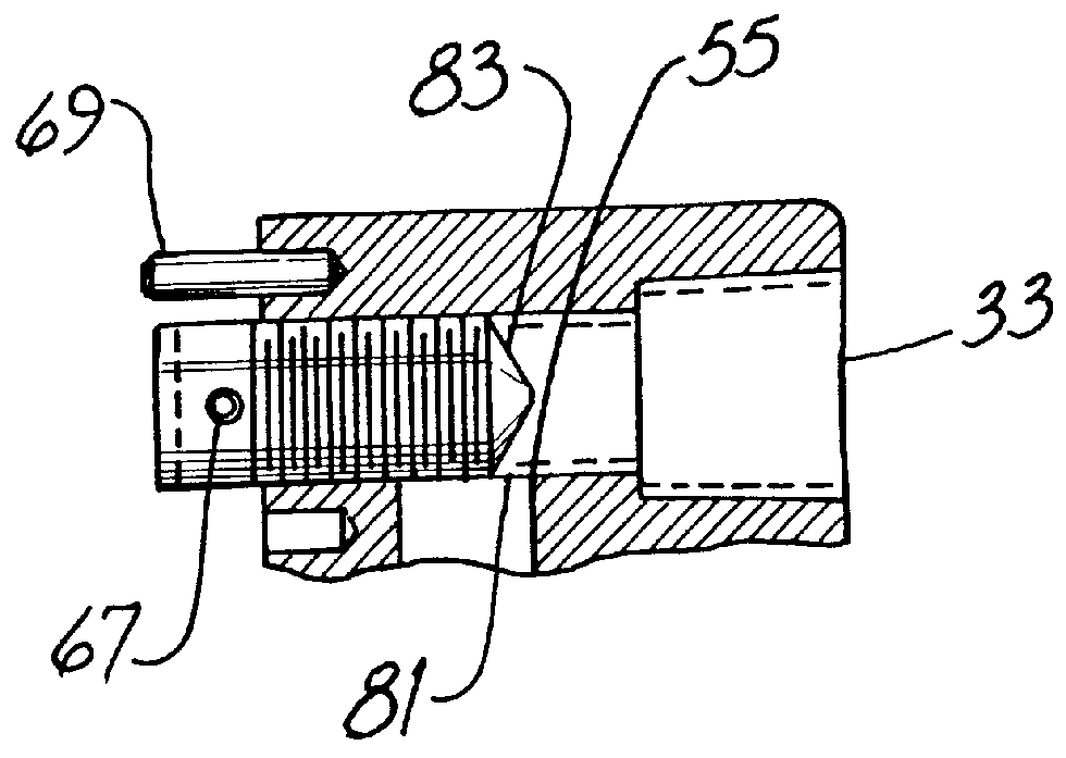
Referring also to FIGS. 2 through 6, the valve 10 includes a block-like orthogonal body 27 having the inlet port 25 and an inlet passage 29 in series with one another and extending along an inlet axis 31. A first outlet port 33 and first outlet passage 35 are also in series with one another and extend along a first outlet axis 37. The port 33 and passage 35 are used when natural gas is the fuel. The inlet port 25 is used irrespective of whether the fuel is natural g...


PUM


Abstract

A valve for flowing gaseous fuel, i.e., natural gas or propane gas, to an internal combustion engine includes a valve body having an inlet passage and first and second outlet paths in parallel with one another and in flow communication with the inlet passage. A plug-type adjustment member is threaded into the body and an annular seat in the body coacts with the adjustment member to form an orifice in the first outlet path. A stop mechanism limits movement of the adjustment member between a first position at which the orifice area is smaller and a second position at which the orifice area is larger. The valve permits adjustment of fuel flow to small engines so that such engines provide maximum power without exceeding applicable emission standards. And the valve is tamper-resistant.

Description

This invention relates generally to internal combustion engines and, more particularly, to regulating fuel flow to such engines.Smaller internal combustion engines have been popular for decades for powering pumps, grass-cutting equipment, pressure washers, standby generators and the like. Earlier in the history of such engine usage, there was little concern about pollution such as exhaust emissions. But the number of smaller engines in use has increased dramatically and concurrent steps were and are being taken by engine manufacturers and state and federal regulators to help assure that air pollution of engine origin is minimized. A particular emission standard is promulgated by the California Air Resources Board (CARB).One way to limit pollution while yet obtaining rated or near-rated horsepower out of the engine is to feed fuel to the engine at a particular rate or at a rate which is within a narrow range of rates. When an engine is to be fueled by a single liquid or gas fuel havi...

Claims


Application Information

Patent Timeline
IPC IPC(8): F02M21/02
CPCF02D19/0647F02D19/0676F02M21/0236F02D19/0613Y02T10/32Y02T10/36F02M21/0212F02M21/0215Y10T137/87901Y10T137/5283Y02T10/30
Inventor HAWORTH, EDWARDCHEN, DAWEIRUEHLOW, GERALD C.
Owner GENERAC POWER SYSTEMS
Why Eureka
Try Eureka