Escape mechanism for water vessel

a technology for escaping mechanisms and water vessels, applied in water conservation, animal watering devices, swimming pools, etc., can solve the problems of reducing the number of patents on this subject, and unable to permit such unwanted guests to escape life-threatening situations

a technology for escaping mechanisms and water vessels, applied in water conservation, animal watering devices, swimming pools, etc., can solve the problems of reducing the number of patents on this subject, and unable to permit such unwanted guests to escape life-threatening situations

US6073583AInactive Publication Date: 2000-06-13CUMMING JOE C

Image

  • Escape mechanism for water vessel
  • Escape mechanism for water vessel
  • Escape mechanism for water vessel

Examples


Embodiment Construction

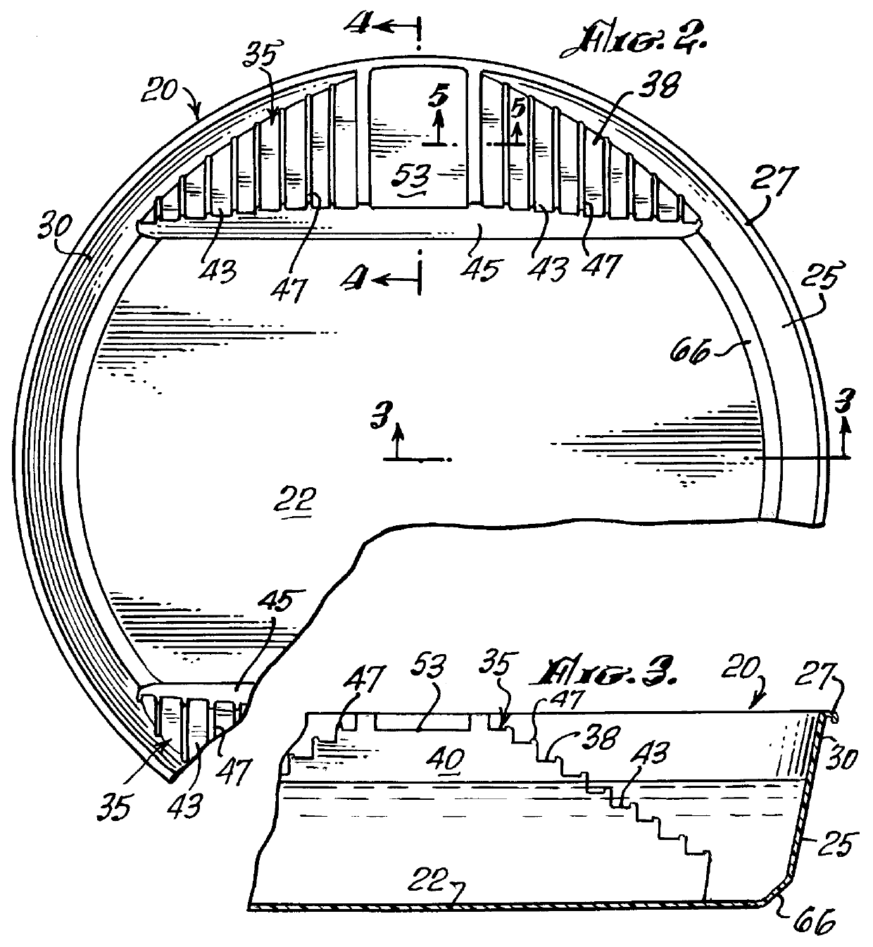
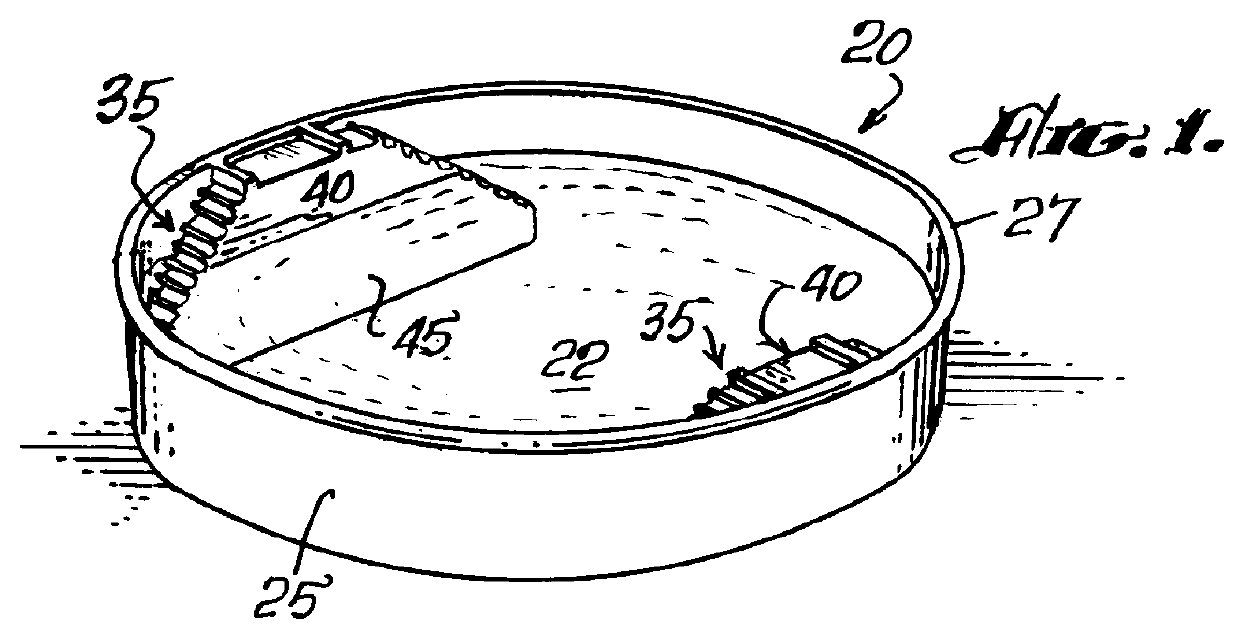
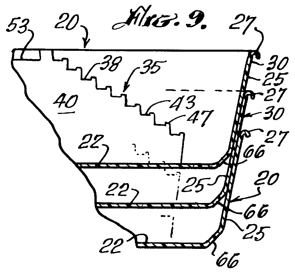
With reference now to the drawings, and initially to FIG. 1, a vessel 20 is illustrated in perspective. The vessel 20 comprises a base member 22 having a geometric configuration, in this case a circle, and an upstanding side wall 25, which is secured to the base in any one of several well known ways, so as to provide a fluid tight seal therebetween. A lip 27 is formed, or otherwise provided along the upper edge 30 of the side wall, more clearly seen in FIG. 3.

It is readily appreciated among farmers and ranchers, and those familiar with the business of raising animals for food and fibre, that water troughs 20, are not, in all cases, cylindrical. Indeed, depending on the cost of manufacture, and transporting such units, they may be any number of well known configurations such as the ellipsoid vessel 206 of FIG. 6, the oval configuration 207 of FIG. 7, or the rectangular configuration 208 of FIG. 8.

The essence of the present invention is found in the provision of means whereby small an...


PUM


Abstract

A vessel for use in providing water, primarily, although not exclusively, for cattle grazing on open range land in which the vessel is provided with an escape mechanism for small animals that might become trapped in the vessel during the course of searching for water, comprising steps, or the like, ascending from the bottom of the vessel to the top, such that a trapped animal might extricate itself by going up the steps.

Description

The present invention relates, generally, to relatively large vessels which provide for the storage and accessability of water for range animals, and more particularly for an escape mechanism for such vessels, which is intended to assist small animals that might inadvertently fall into such vessels during efforts to obtain water therefrom.FIELD OF THE INVENTIONSince the western United States was first settled, the propagation and raising of animals for food and clothing has been a major industry. In current times, such animals are more domesticated and less self reliant. Coincidently, natural resources, and in particular water, is in significantly less supply, particularly on the open range, than it once was.In light of the lack of an abundant supply of water, for example, it is not uncommon for a rancher to provide water for his animals as they graze on the open range, much in the same manner as he would if those cattle were corralled.The open pasture lands are typically shared wit...

Claims


Application Information

Patent Timeline
13 Jun 2000
Publication
US6073583A
IPC
A01K61/00; E03B3/00; E03B3/03; E04H4/14; E04H4/00
CPC
A01K7/00; E04H4/144; E03B3/03; A01K61/00; Y02A20/108; A01K29/00; Y02A20/00; Y02A40/81
Inventors
CUMMING, JOE C.