Adsorption apparatus and methods

a technology of adsorption apparatus and adsorption filtering system, which is applied in the direction of lighting and heating apparatus, heating types, separation processes, etc., can solve the problems of contaminating the air and other processes in the room, using these substances,

Inactive Publication Date: 2000-09-05
DONALDSON CO INC
View PDF46 Cites 60 Cited by
  • Summary
  • Abstract
  • Description
  • Claims
  • Application Information

AI Technical Summary

Benefits of technology

The invention of application Ser. No. 08 / 890,804 is directed to an adsorptive filtering device and in particular to an adsorptive device that provides for balanced distribution through adsorptive beds, increased life and improved efficiency.
Each adsorption bed assembly includes a housing having a planar top and bottom. Openings are formed in the top and bottom that allow air flow through adsorption bed elements within the housing. The upper surface includes a single planar member with flanges bent down to form openings. Within the housing are disposed rectangular adsorption beds which include a mesh screen retaining activated carbon or other adsorptive materials therebetween. The mesh screens include channel members extending around the periphery of each element which are potted to the ends of the inside of the housing. The screens also include a center post which prevents the screens from bowing outward under pressure. The channels at the edge of the element have a midbed baffle which extends inward into the adsorptive material. The baffle ensures that voids at the edge of the medium do not decrease the efficiency of the bed as the length of the path for gases passing along the edge are increased by the baffle extending inward. Similarly, the post at the center may include a flange extending transversely to the post to increase the length of the path of air passing along the center post. Each element also includes a pre-filter and post-filter, typically an electrostatic type filter for retaining particles from the adsorptive material. The adsorption elements are arranged in a V-type cross-sectional configuration which provides for even distribution and pressure drop for each individual element.

Problems solved by technology

The use of these substances presents a problem because vapors that are present or are a byproduct from the process may contaminate the air and other processes in the room, such as lithography processes using chemically amplified photoresists, if not properly removed.

Method used


Image

  • Adsorption apparatus and methods
  • Adsorption apparatus and methods
  • Adsorption apparatus and methods

Examples


Embodiment Construction

. NO. 08 / 890,804

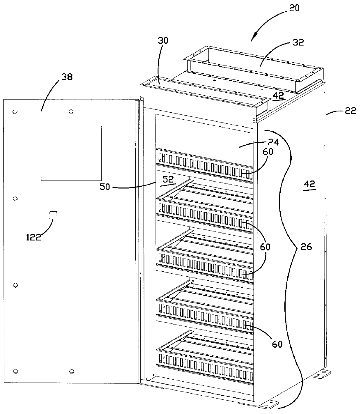
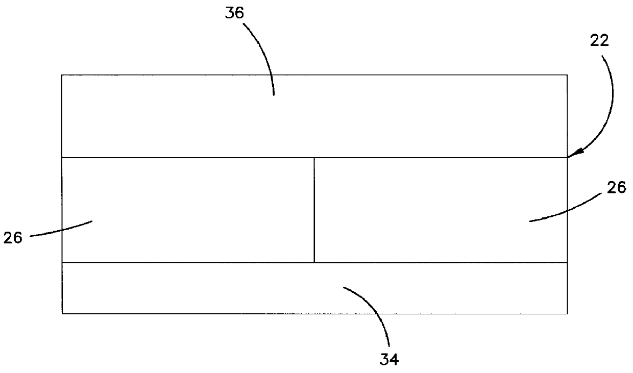
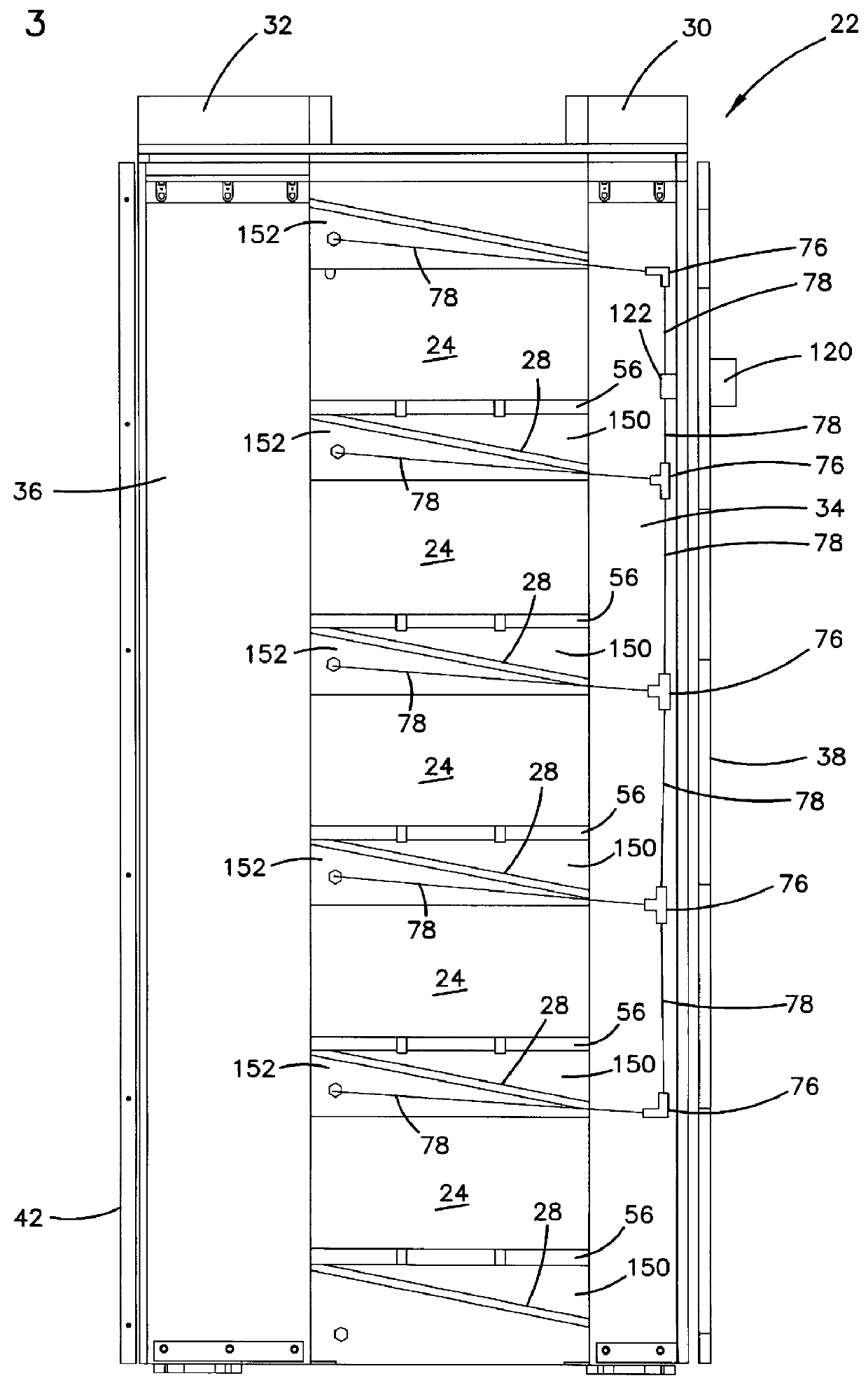
Referring now to the drawings, and in particular to FIG. 1, there is shown a counter flow adsorption module 22 of an adsorptive filtering system 20. The modules 22 can be joined together to form a higher capacity adsorptive system 20, as shown in FIG. 2. The system 20 provides for a plurality of cartridge-type adsorption bed assemblies 24 receiving parallel flow with both vertical stacking shown most clearly in FIG. 1, as well as horizontal stacking, as shown in FIG. 2. With the present configuration, the height and width of the number of adsorption bed assemblies 24 can be designed to accommodate the filter and flow requirements of each particular system.

Referring again to FIG. 1, each module 22 includes an inlet 30 and an outlet 32 having flanges formed thereon for accepting a gasket and providing a sealed connection to upstream and downstream duct work. The counter flow adsorption module 22 includes an access door 38 pivoting along one vertical edge in a preferred...


PUM

PropertyMeasurementUnit
thickaaaaaaaaaa
thickaaaaaaaaaa
diameteraaaaaaaaaa

Abstract

An adsorption bed arrangement includes a plurality of adsorption elements, a housing, and a gasket member. Each of the adsorption elements has adsorption media contained within a respective element. Each of the adsorption elements are selectively openable to provide access to the adsorption media. The housing defines an interior, a plurality of inlet openings, and a plurality of outlet openings. The plurality of adsorption elements are positioned within the housing interior. The housing is selectively openable to provide access to the plurality of adsorption elements. The gasket member is between the housing and the adsorption elements. A method for changing filtering media in an adsorption apparatus includes steps of removing an access panel from an adsorption bed housing to expose a cover member covering an end of an adsorption element; removing the cover member from the end of the adsorption element to expose filtering media within the element; and pouring the filtering media from the element.

Description

1. Field of the InventionThe present invention relates to an adsorption bed and adsorption filtering system for removing airborne contaminants from clean rooms, sick buildings, or other enclosed spaces.2. Related ArtGas adsorption beds are used in many industries to remove airborne contaminants, such as organic bases, to protect people, the environment and often, a critical manufacturing process or the products that are manufactured. A specific example of an application for gas adsorption beds is the semiconductor industry where products are manufactured in an ultra-clean environment, commonly known in the industry as a "clean room". The manufacturing processes typically require the use of substances such as solvents to be used in the clean room environment. The use of these substances presents a problem because vapors that are present or are a byproduct from the process may contaminate the air and other processes in the room, such as lithography processes using chemically amplified...

Claims


Application Information

Patent Timeline
Patent Type & Authority Patents(United States)
IPC IPC(8): B01D53/04F24F3/16B01D46/12
CPCB01D46/125B01D53/0446F24F3/161B01D2259/40084B01D2259/4508F24F3/167B01D46/121
Inventor GRAHAM, KRISTINE M.PETERSON, PAULMONSON, DONALD R.MILLS, JARREN B.GRAFE, TIMOTHY H.
Owner DONALDSON CO INC
Why Eureka
Try Eureka