Measuring machine

a measuring machine and measuring plate technology, applied in mechanical measuring arrangements, instruments, manufacturing tools, etc., can solve problems such as uneven temperature distribution inside the machine, and deterioration of geometric accuracy

Inactive Publication Date: 2002-04-16
MITUTOYO CORP
View PDF10 Cites 27 Cited by
  • Summary
  • Abstract
  • Description
  • Claims
  • Application Information

AI Technical Summary

Benefits of technology

According to the above arrangement, since the main structural member of the moving mechanism is made of aluminum or aluminum alloy including aluminum as main component, which have large thermal conductivity, temperature tracking ability against the temperature change can be improved, thereby making uniform temperature distribution of the entire machine.
According to the above, since the heat from the controller can be discharged to the outside by the fan, the bad influence by the heat can be restrained to the utmost, thereby also guaranteeing geometrical accuracy in temperature change.

Problems solved by technology

However, since the conventional measuring machine uses different material having rigidity required for respective portions, geometrical accuracy in temperature change is deteriorated.
Since the conventional measuring machine uses different material having rigidity required for respective portions, thermal conductivity differs in respective portions, thereby making the temperature distribution inside the machine uneven to deteriorate geometrical accuracy.
Since members having different thermal expansion coefficient are directly attached in respective portions of the conventional measuring machine, the expansion amount of respective members differ when the temperature changes, thereby causing the deterioration of the geometrical accuracy.
However, the temperature correcting function can not effectively performed as long as the aforesaid problem (deterioration of geometrical accuracy in temperature change) is not solved.

Method used


Image

  • Measuring machine
  • Measuring machine
  • Measuring machine

Examples


Embodiment Construction

)

An embodiment in which a measuring machine according to the present invention is applied to a three-dimensional measuring machine will be described below.

[General Arrangement]

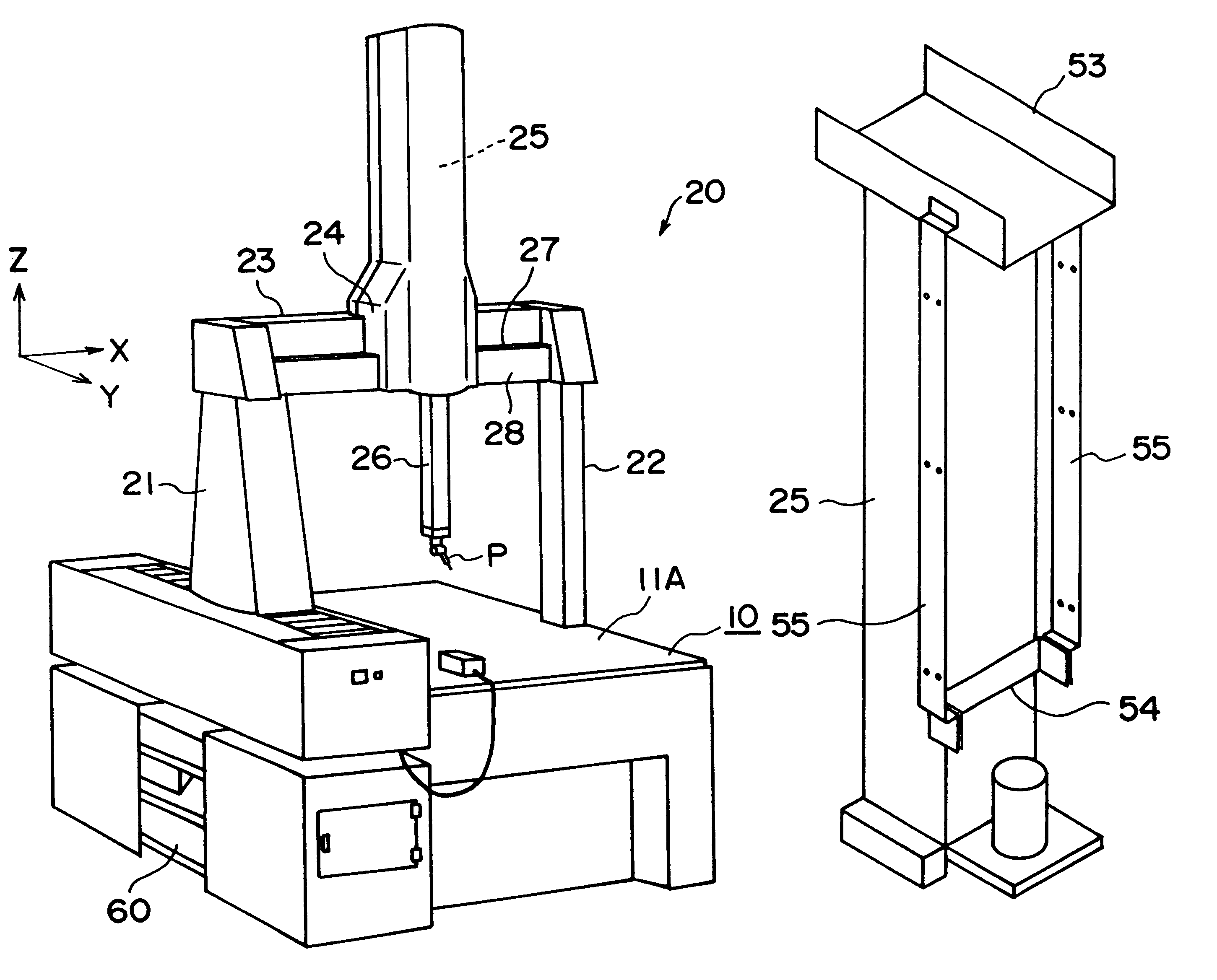
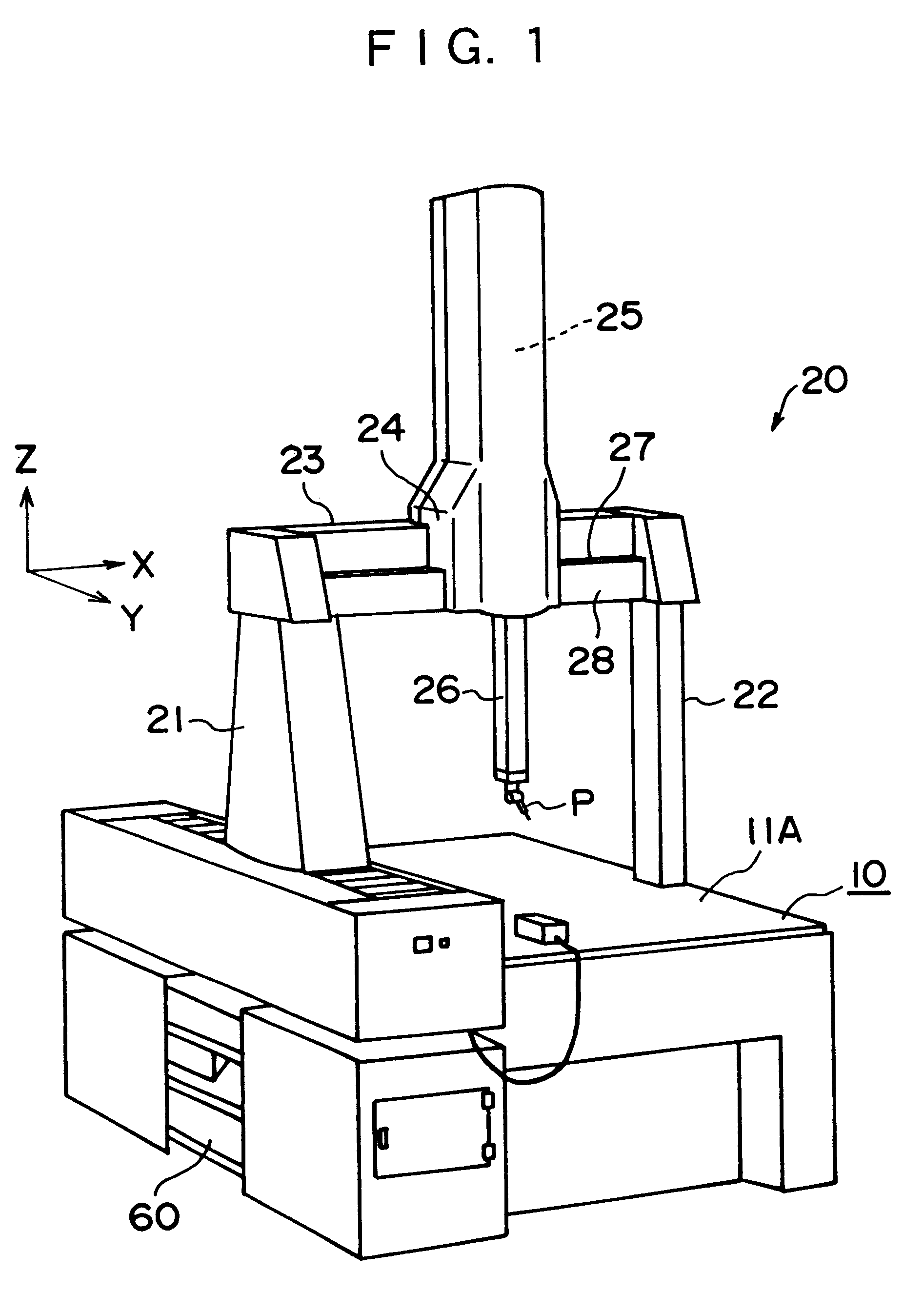
As shown in FIG. 1, the three-dimensional measuring machine according to the present invention has a base 10, a touch signal probe P as a probe, a moving mechanism 20 for moving the touch signal probe P in three-dimensional directions (X, Y and Z-axis directions) relative to the base 10, and a controller 60 for controlling the movement of the moving mechanism 20 and for acquiring coordinates values of respective axes (X, Y and Z-axis) when the touch signal probe P contacts a workpiece to measure a dimension etc. of the workpiece based on the coordinates values.

The moving mechanism 20 has a column 21 and a supporter 22 disposed on both sides of the base 10 movably in back and forward direction (Y-axis direction), a X-beam 23 spanning over upper ends of the column 21 and the supporter 22, a slider 24 disposed al...


PUM


Abstract

A measuring machine having a base (10), a touch signal probe (P), a moving mechanism (20) for retaining the touch signal probe (P) movably in three-dimensional directions, and a controller (60) for controlling a movement of the moving mechanism (20) and for acquiring coordinates value of respective axes based on a contact signal from the touch signal probe (P) to measure a dimension etc. of a workpiece based on the coordinates value is provided. Main structural members structuring the moving mechanism (20), more specifically, a column (21), a supporter (22), a X-beam (23), a Z-axis structure (25) and a Z-axis spindle (26) are made of aluminum or aluminum alloy including aluminum as main component, which has large thermal conductivity, thereby making temperature distribution uniform to improve geometrical accuracy.

Description

1. Field of the InventionThe present invention relates to a measuring machine such as a three-dimensional measuring machine and coordinates measuring machine. More specifically, it relates to a measuring machine having a base, a probe and a moving mechanism for relatively moving the base and the probe, in which accuracy with respect to temperature change is guaranteed, and furthermore, a accuracy-guaranteed temperature range can be extended.2. Description of Related ArtConventionally, a measuring machine such as three-dimensional measuring machine and coordinates measuring machine has been known for measuring profile and dimension of a workpiece. Generally, such measuring machine has a base, a probe, a moving mechanism for moving the probe relative to the base in three-dimensional directions (X, Y and Z-axis directions), and a controller for; controlling the movement of the moving mechanism; for acquiring coordinate value of respective axes when the probe contacts the workpiece and;...

Claims


Application Information

Patent Timeline
Patent Type & Authority Patents(United States)
IPC IPC(8): G01B5/00G01B5/008G01B21/00
CPCG01B5/008G01B5/0011
Inventor KIKUCHI, SHIGEO
Owner MITUTOYO CORP
Why Eureka
Try Eureka