Power transfer device

a power transfer device and power technology, applied in the direction of magnetically actuated clutches, mechanical actuated clutches, transportation and packaging, etc., can solve the problems of harmful noise and harmful nois

Inactive Publication Date: 2004-04-20
TOYODA MASCH WORKS LTD
View PDF6 Cites 15 Cited by
  • Summary
  • Abstract
  • Description
  • Claims
  • Application Information

AI Technical Summary

Problems solved by technology

In use of the power transfer device in a four wheel drive vehicle, harmful noises will occur if differential rotation of the rotary members is reversed in a condition where the main clutch is being engaged by the thrust force applied from the cam mechanism.
In such an instance, there will occur harmful noises due to clearances at the splined portions of the component parts, defacement of the component parts or a cam angle of the cam mechanism.

Method used


Image

  • Power transfer device
  • Power transfer device
  • Power transfer device

Examples


Embodiment Construction

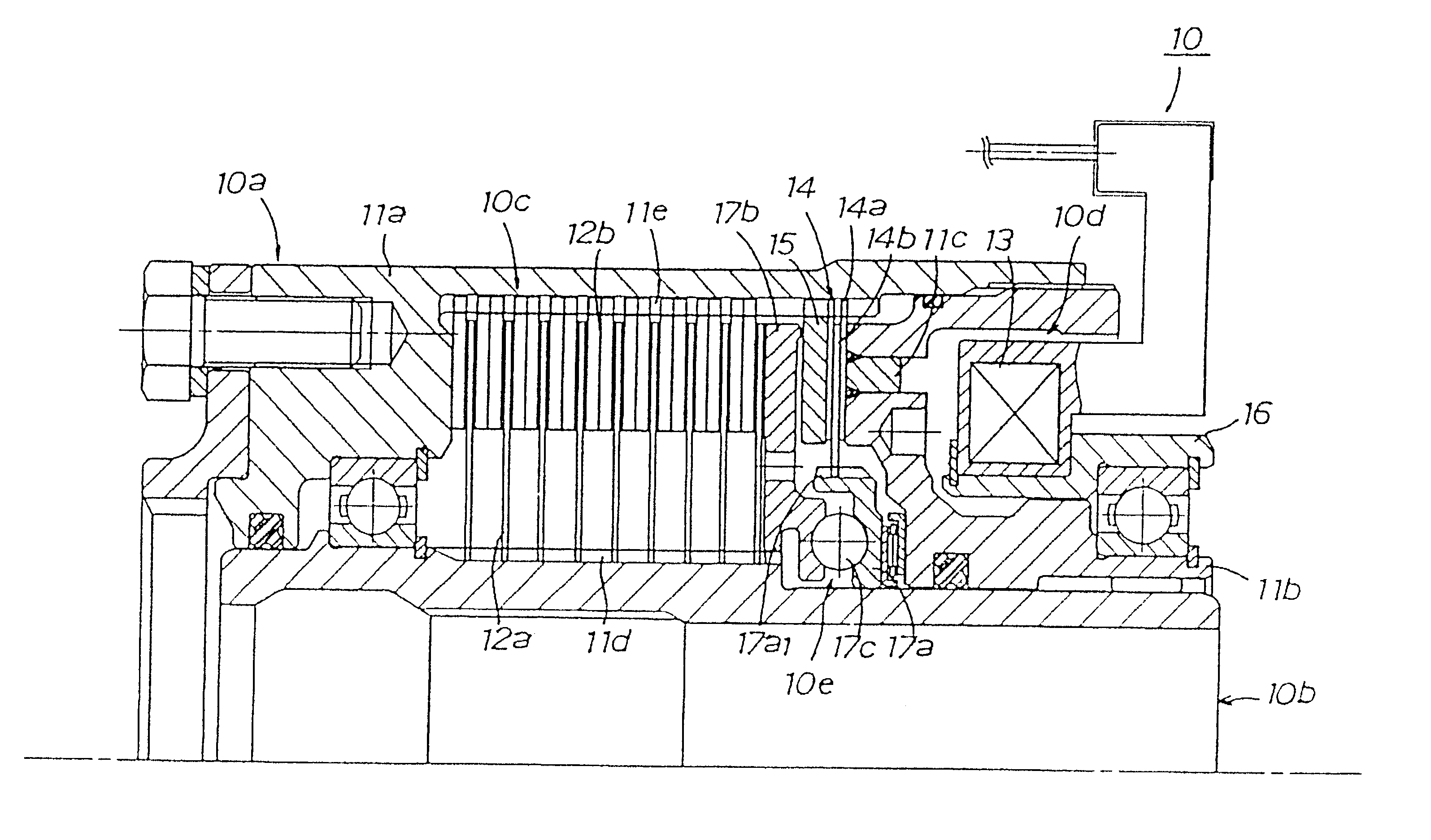
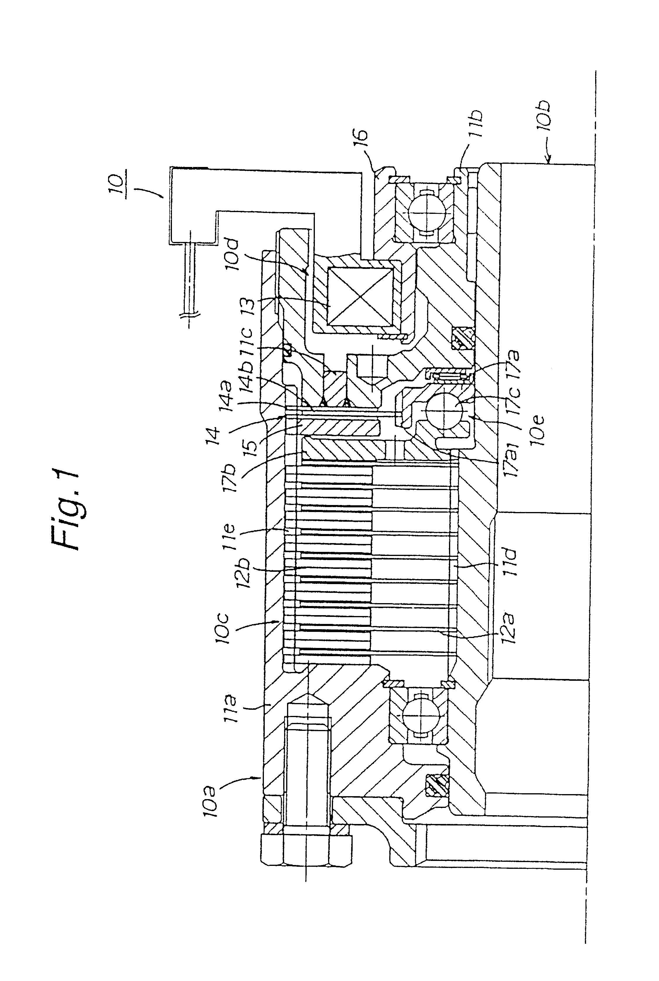
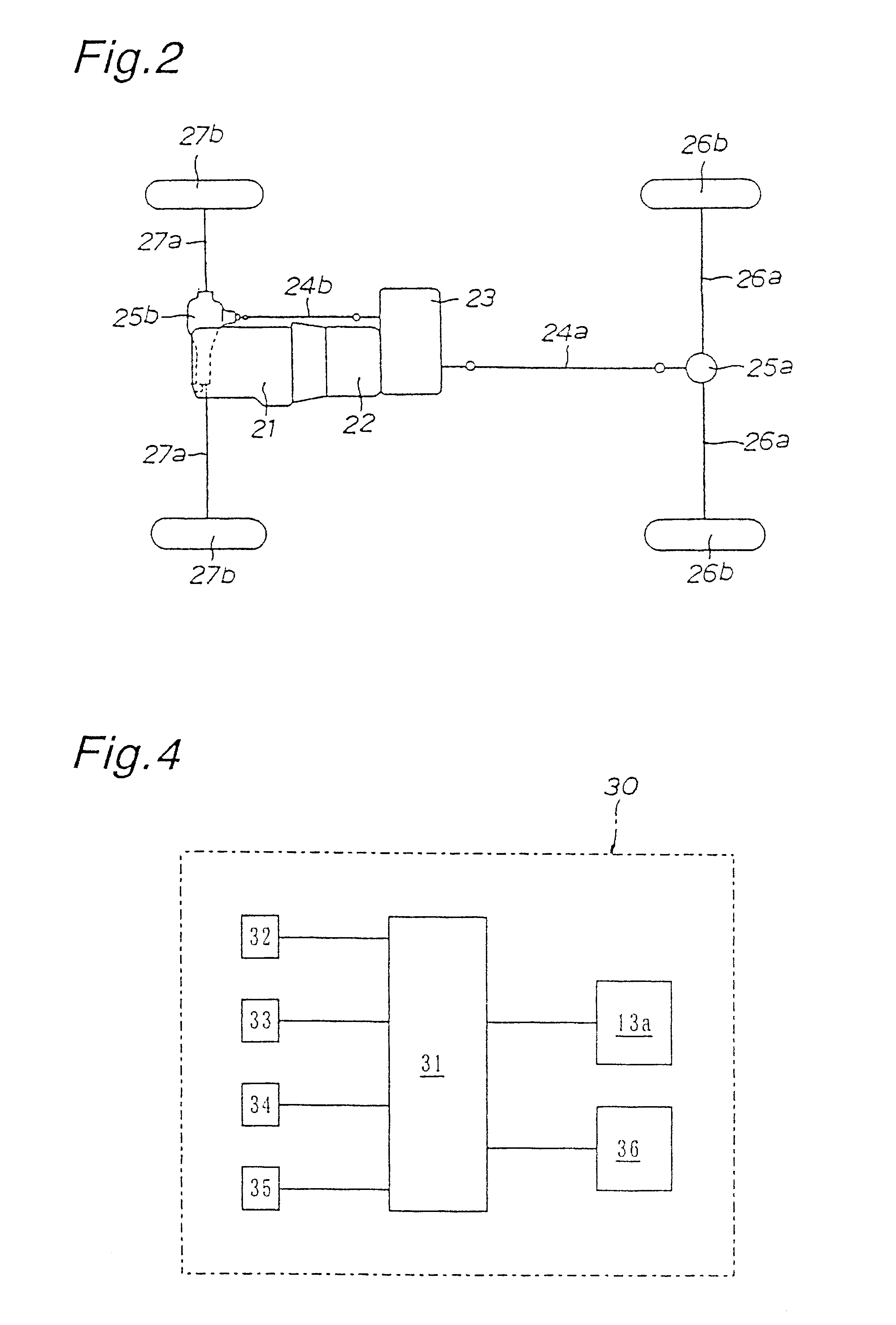
Illustrated in FIG. 1 is an embodiment of a power transfer device 10 in accordance with the present invention. As shown in FIG. 2, the power transfer device 10 is mounted on a four-wheel drive vehicle of the rear wheel driven type. The four wheel drive vehicle has a transfer assembly 23 mounted to a transmission 22 in drive connection to a prime mover 21. The transfer assembly 23 is placed between rear and front propeller shafts 24a and 24b for continually transferring drive power of the prime mover 21 to the rear propeller shaft 24a and for transferring the drive power to the front propeller shaft 24b when conditioned to establish drive connection between the propeller shafts 24a and 24b.

In a condition where the rear propeller shaft 24a is disconnected from the front propeller shaft 24b, the drive power of the prime mover 21 is transferred to a set of rear axle shafts 26a, 26a from the rear propeller shaft 24 through a rear differential 25a to drive a set of rear road wheels 26a, 2...


PUM


Abstract

A power transfer device including a main clutch, a cam mechanism and an electromagnetic pilot clutch mechanism coaxially assembled within a cylindrical space between an external cylindrical rotary member and an internal rotary member, wherein an electromagnetic coil of the pilot clutch mechanism is applied with an electric current to produce pilot torque, the cam mechanism is applied with the pilot torque to produce thrust force in an axial direction, and the main clutch is engaged by the thrust force applied from the cam mechanism to effect drive connection between the rotary members. In the power transfer device, residual thrust force of the cam mechanism is electrically or mechanically decreased at an instance when differential rotation of the rotary members is reversed.

Description

BACKGOURND OF THE INVENTION1. Field of the InventionThe present invention relates to a power transfer device adapted for use in an automotive vehicle.2. Discussion of the Prior ArtDisclosed in Japanese Patent Laid-open Publication 2000-234635 is a power transfer device of this kind which comprises a main clutch, a cam mechanism and an electromagnetic pilot clutch mechanism coaxially assembled within a cylindrical space between an external cylindrical rotary member and an internal rotary member. In the power transfer device, an electromagnetic coil of the pilot clutch mechanism is applied with an electric current to produce a pilot torque, the cam mechanism is applied with the pilot torque to produce thrust force in an axial direction, and the main clutch is engaged by the thrust force applied from the cam mechanism to effect transmission of a driving torque between the rotary members.In use of the power transfer device in a four wheel drive vehicle, harmful noises will occur if diff...

Claims


Application Information

Patent Timeline
Patent Type & Authority Patents(United States)
IPC IPC(8): F16D27/10F16D27/115F16D28/00F16D48/12B60K23/04
CPCF16D27/115
Inventor TAKUNO, HIROSHISAITO, YASUNARI
Owner TOYODA MASCH WORKS LTD
Why Eureka
Try Eureka